

Новое поступление

50 pcs Nillkin Qin leather case uses superior natural texture mobile phone For Apple iPhone 7 |

Силиконовый мягкий чехол с принтом армейского солдата из ТПУ для samsung Galaxy J1 J2 J3 J4 J5

Cool School Bags Boys Marvel Avengers Five Nights at Freddy Backpack For Teenagers Bag Gift Girls Student Bookbag |

Пеньюар женский прозрачный с длинным рукавом AW80759 | Женская одежда
1 094,92 - 1 202,21 руб.

Спортивный костюм мужские зимние спортивные костюмы комплекты Мужская теплая

Брелок для автомобильных ключей с ручкой видеоигр в подарок Fiat 500 500x ducato типо
70,76 руб.

Карбюратор для DELLORTO 14 12 мм SHA мопед Carb Tomos итальянский мопедов |
1 240,25 руб.

ETAxopowo Store
Магазина ETAxopowo Store работает с 21.03.2021. его рейтинг составлет 93.97 баллов из 100. В избранное добавили 789 покупателя. Средний рейтинг торваров продавца 4.8 в продаже представленно 888 наименований товаров, успешно доставлено 1351 заказов. 929 покупателей оставили отзывы о продавце.
Характеристики
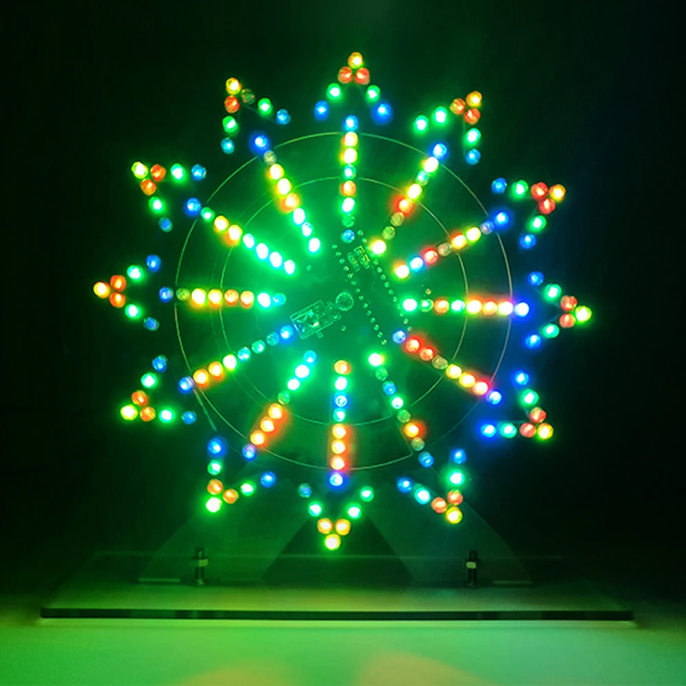
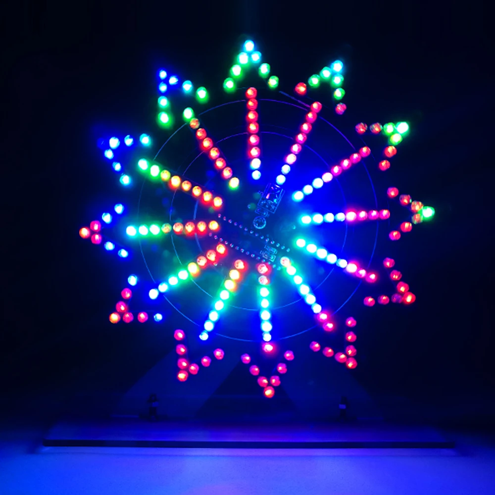
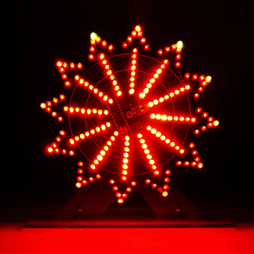
DIY electronice kit LED rotating ferris wheel circuit learning soldering 16kinds flashing mode remote control 5V input |
История изменения цены
*Текущая стоимость 1 342,97 уже могла изменится. Что бы узнать актуальную цену и проверить наличие товара, нажмите "Добавить в корзину"
| Месяц | Минимальная цена | Макс. стоимость | Цена |
|---|---|---|---|
| Sep-18-2025 | 1597.2 руб. | 1677.8 руб. | 1637 руб. |
| Aug-18-2025 | 1584.70 руб. | 1663.20 руб. | 1623.5 руб. |
| Jul-18-2025 | 1329.42 руб. | 1395.2 руб. | 1362 руб. |
| Jun-18-2025 | 1557.77 руб. | 1635.14 руб. | 1596 руб. |
| May-18-2025 | 1355.8 руб. | 1423.22 руб. | 1389 руб. |
| Apr-18-2025 | 1530.45 руб. | 1607.98 руб. | 1568.5 руб. |
| Mar-18-2025 | 1516.0 руб. | 1592.47 руб. | 1554 руб. |
| Feb-18-2025 | 1503.4 руб. | 1578.37 руб. | 1540.5 руб. |
| Jan-18-2025 | 1490.93 руб. | 1565.13 руб. | 1527.5 руб. |
Описание товара


Feature
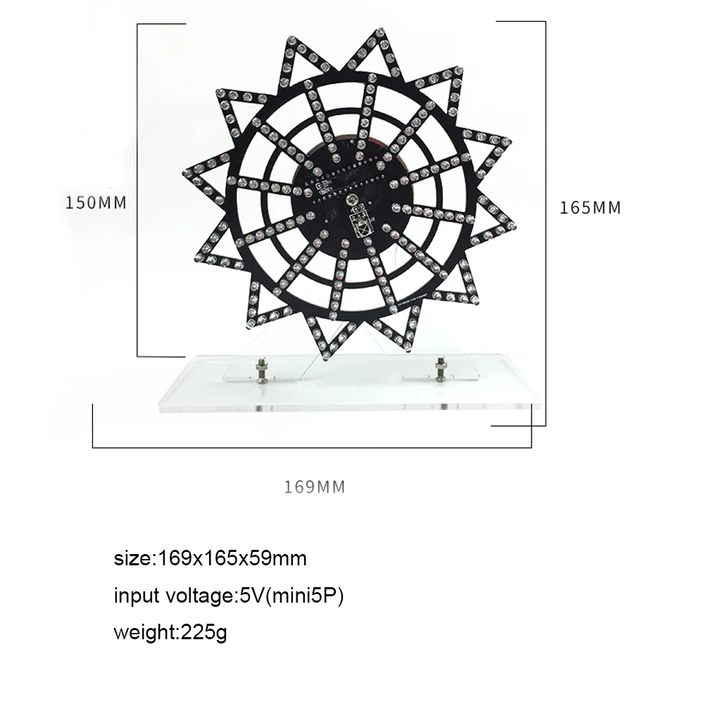
1.input voltage:5V
2.remote control function:
flash speed: press TEST-( 3+)( 6 -)
Flash mode: press 1/4/7
Caution!!
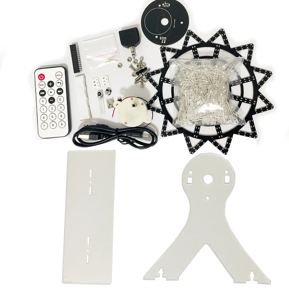
1. this is DIY electronic soldering kit for hobby beginners to learn and practice welding , not finished product !!! Please understand it!
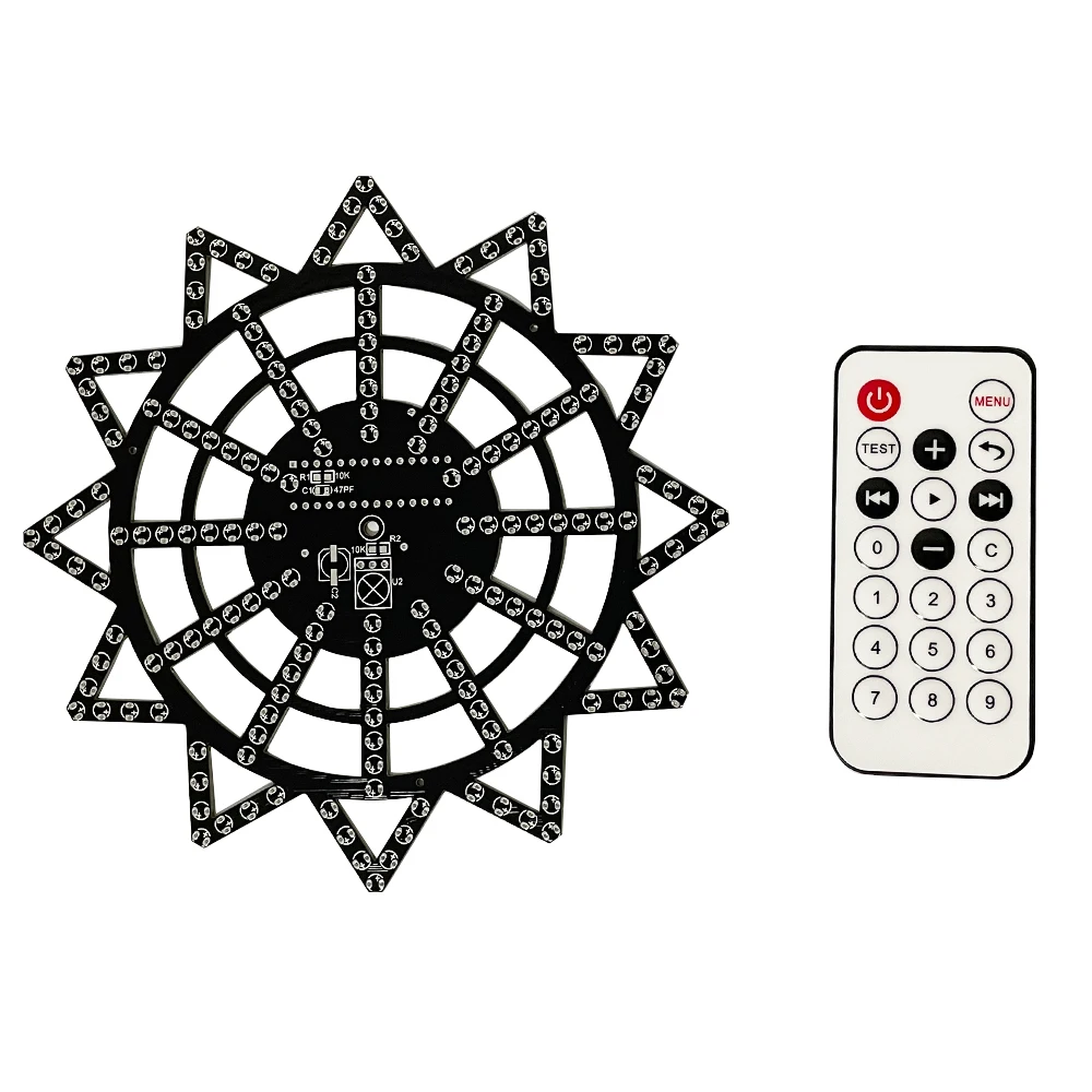
2. The diameter of the PCB just SAME as decribe 15cm. Please don't imagine it is very very big!!
PLS understand the product before payment ,thank you!
Suitable for electronic DIY hobby beginners to learn and practice welding.It is widely used in schools to help students learn basic mechanical and electronic skills.


Installation tutoria:
Tool
1.Electric soldering iron with about 35w power
2.Soldering tin
3.Tweezers
4.Electronic pliers
5.Screwdriver welding
Steps:
1. Solder chip resistors and capacitors (no direction)
2. Weld plug-in led (note the direction)
3. Weld infrared Receiver (note the direction)
4. Weld the MCU (note the direction)
5. Weld the thimble (note the direction) Weld the chip resistors and capacitors, these two components have no positive and negative poles, use tweezers to clamp the welding when welding, R1, R2 welding 10K resistor (the word 103 is written on the resistor), C1 is soldered with a 47pf capacitor. (No direction) C2 welding 220uf electrolytic capacitor (note the direction)
1.Welding the led, the led has a positive and negative pole, the long lead of the led is the positive pole, insert the pad with the + sign on the circuit board tightly, it is recommended to plug the led in and press it and then weld, so that the led is relatively neat, two when welding the led The pins are soldered separately, and soldering together will easily cause the led to burn out.

2.Solder the infrared receiver, bend the component pins 90 degrees and solder.

3.3.Solder the chip, insert the recess of the chip corresponding to the recess of the printing silk, do not short-circuit each pin of the chip during soldering, (determine the direction before soldering, the chip cannot be removed by wrong soldering, and the whole board is scrapped)

4.Soldering the thimble, the thimble must be completely pressed against the circuit board, and not crooked (note the direction, and the chip is in the same direction)

5.The power supply board is welded, and the pins of the usb socket must be separated and not short-circuited,red wire and black wire is connect to the motor, you can connect clockwise or counterclockwise according to your preference.test inadvance.

6.Assemble holder, first tear off the protective film on the shell,
Screw the power supply board, motor, and casing together with screws, with the casing in the middle, insert the screws from the power supply board, and then use oil and other lubricating oil to add smoothness to the three silver circles


Смотрите так же другие товары: