100шт/набор Разъемный провод Дюпон с шагом 2,54 мм, 1 контакт, однорядный, женский, для on.
149.51

Новое поступление

Магазина Shop5607256 Store работает с 27.01.2020. его рейтинг составлет 78.05 баллов из 100. В избранное добавили 101 покупателя. Средний рейтинг торваров продавца 4.3 в продаже представленно 824 наименований товаров, успешно доставлено 127 заказов. 41 покупателей оставили отзывы о продавце.
Характеристики
*Текущая стоимость 7590.97 уже могла изменится. Что бы узнать актуальную цену и проверить наличие товара, нажмите "Добавить в корзину"
| Месяц | Минимальная цена | Макс. стоимость | Цена |
|---|---|---|---|
| Sep-17-2025 | 9032.78 руб. | 9484.27 руб. | 9258 руб. |
| Aug-17-2025 | 8956.44 руб. | 9404.81 руб. | 9180 руб. |
| Jul-17-2025 | 7514.88 руб. | 7890.11 руб. | 7702 руб. |
| Jun-17-2025 | 8804.60 руб. | 9244.45 руб. | 9024 руб. |
| May-17-2025 | 7666.65 руб. | 8049.11 руб. | 7857.5 руб. |
| Apr-17-2025 | 8653.42 руб. | 9086.39 руб. | 8869.5 руб. |
| Mar-17-2025 | 8577.78 руб. | 9006.81 руб. | 8791.5 руб. |
| Feb-17-2025 | 8501.29 руб. | 8926.24 руб. | 8713.5 руб. |
| Jan-17-2025 | 8425.74 руб. | 8846.53 руб. | 8635.5 руб. |
Описание товара


Chapter 1 Product Introduction
One.Overview
MB4AI4AO 4-channel analog quantity acquisition and 4-channel analog quantity output module, can collect 4-channel 0-20mA, 4-20mA, 0-5V, 0-10V four analog input signals and 4-channel 0-20mA, 4-20mA, Four analog signal outputs of 0-5V and 0-10V; the analog signal data collected by 4AI is output through the isolated RS485 interface, and the data output of 4AO can be controlled through the isolated RS485 interface; the module uses Modbus-RTU communication, which can be directly Equipped with PLC, DCS and various domestic configuration software.
Signal acquisition, signal output, power supply, and RS485 communication electrical signals are isolated from each other, effectively suppressing various types of series mode and common mode interference, ensuring the accuracy of the data, and also ensuring the reliable operation of the module.
two.Features
1.Adopt standard Modbus-RTU protocol.
2.The input signal type of each channel can be set according to your needs.
3.AOanalog output working mode
Module function mode | Features |
Load preset value mode at power-on | 1.Analog output [AOinitial power-on value] can be set to load a value, the default is to load0value. 2.When the module is powered on, the analog outputAO isloaded with [AOpower on initial value]. |
Power-up load power-down value mode | 1.Continuously monitor the power supply of the module. When it detects that the power supply of the module is powered off, record and save the currentAOchannel output value. 2.When the module is powered on again, the analog outputAOloads the value before the last power-off. |
Isolator mode (Safety barrier working mode) | 1.The output size of theanalog outputAO0is determined by the value of AI0. 2.Theoutput value ofAO0changes with the value of AI0, and the output is not changed by computer control 3.Several other channels and so on |
4.Safety: signal acquisition, signal output, power supply, RS485 communication electrical signals are isolated from each other.
5.Communication protection: RS485 communication signal output interface adopts over-voltage and over-current double protection.
6.Input signal type, output signal type, communication format can be set by software.
7.Power polarity protection.
three.Technical index
project | parameter |
AI signal input | 1.Input channel: 4-channel isolated analog quantity acquisition 2.Input signal type: 0 ~ 20mA, 4 ~ 20mA, 0 ~ 5V, 0 ~ 10V four analog signals 3.Sampling rate: 4 channels are collected every 5mS 4.Resolution: 12 bit 5.Accuracy: voltage 0.2% current 0.3% 6.Isolation voltage protection: 1500V |
AO Signal output | 1.Output channel: 4-channel isolated analog output 2.Output signal type:0 ~ 20mA, 4 ~ 20mA, 0 ~ 5V, 0 ~ 10V four analog signals 3.Sampling rate: 4 channels 5mS can be updated once 4.Resolution: 12 bit 5.Acquisitionaccuracy: voltage 0.2% current 0.3% 6.Isolation voltage protection: 1500V |
RS485 Communication output | 1.Communication protocol: MODBUS-RTU 2.Interface type: isolated RS485 communication, output interface adopts over-voltage and over-current double protection 3.Baud rate: 1200bps, 2400bps, 4800bps, 9600bps, 19200bps 4.Check digit: no check, even check, odd check 5.Setting method: module address, baud rate, parity bit can be set by software 6.Isolation voltage protection: 1500V |
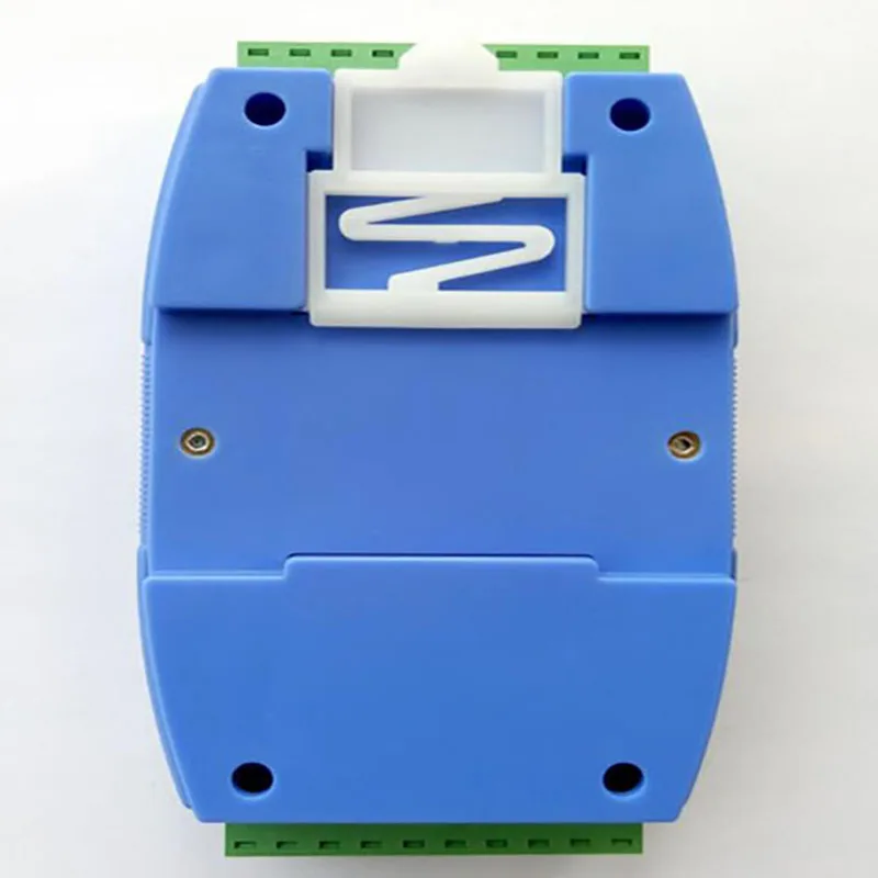
Module size | A.Individual module size: 104mm * 72mm * 26mm B.Box with terminal and rail size: 124mm * 72mm * 45mm |
Installation method | Standard DIN rail installation (35mm rail or high and low rail) |
working environment | Temperature: -10 ~ + 55 ℃ Humidity: 35% to 85% (no condensation) |
Working power | 1.Power supply voltage: 10V ~ 30V wide range power supply, with power supply polarity protection 2.Power consumption: less than 4W |
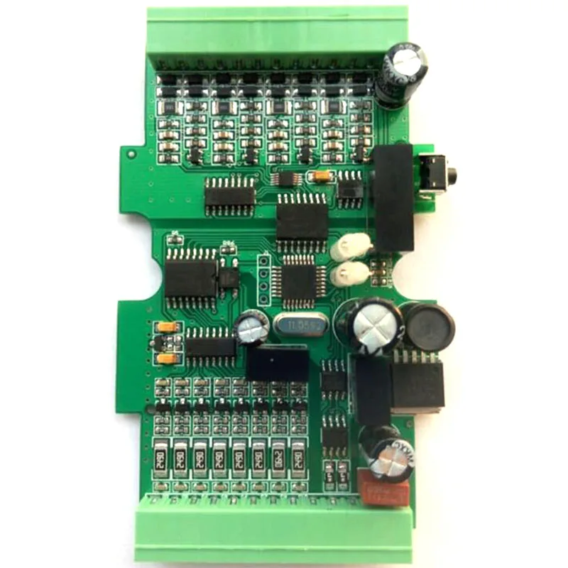
four.Product appearance and peripheral wiring diagram

Fives.Module indicator and switch function description
1.POW / SET;module working status indication
A.Green light is on: the module is working.B. Red light is on: the module has configuration parameters written, need to power on again.
2.TXD / RXD:communication status indication
A.Green light flashes: data is received by communication B. Red light flashes: module is sending data
C. Thegreen light is always on: the communication RS485 line connected to DATA + and DATA- is reversed or the connection is broken.
3.Reset switch on the right side of the module
A.When the communication parameters (module address, baud rate, parity bit) are unknown or the communication parameters are set incorrectly, it is not possible to establish contact with the module communication. The solution is to reset the communication parameters; we use a paper clip to press and hold the reset switch. Release, after 5 seconds, the module [POW / SET] red indicator lights, release the reset switch, the communication parameters have been reset, as long as the power of the module is powered off and restarted once, the communication parameters of the module have been reset.
B.Communication parameters after reset: address: 1, baud rate: 9600bps, parity: none.
six.Typical application wiring diagram

Seven.Terminal definition
Terminal | name | Explanation | Terminal | name | Explanation | |
1 | AI0 | Analog input 0 channel positive terminal | 14 | A00I | Analog channel 0 current output | |
2 | AI1 | Analog input 1 channel positive terminal | 15 | A00V | Analog channel 0 voltage output | |
3 | AI2 | Analog input 2 channel positive terminal | 16 | AOGND | Analog channel 0 output negative terminal | |
4 | AI3 | Analog input 3 channel positive terminal | 17 | A01I | Analog channel 1 current output | |
5 | AIGND | Analog input negative terminal | 18 | A01V | Analog channel 1 voltage output | |
6 | AIGND | Analog input negative terminal | 19 | AOGND | Analog channel 1 output negative terminal | |
7 | AIGND | Analog input negative terminal | 20 | A02I | Analog channel 2 current output | |
8 | AIGND | Analog input negative terminal | twenty one | A02V | Analog channel 2 voltage output | |
9 | NC | air | twenty two | AOGND | Analog channel 2 output negative terminal | |
10 | DATA + | RS485communication + | twenty three | A03I | Analog channel 3 current output | |
11 | DATA- | RS485communication- | twenty four | A03V | Analog channel 3 voltage output | |
12 | + Vs | Power input + | 25 | AOGND | Analog channel 3 output negative terminal | |
13 | GND | power input- | 26 | AO24V | Analog output 24V power supply positive terminal |
Eight.Principle block diagram

nine.MODBUSregister description
1.MODBUS function code supported by the module
Code | meaning | operating |
0x03H | Read multiple holding registers | Read the value of one or more holding registers |
0x 06H | Write a single holding register | Write a data to holding register |
0x 04H | Read multiple input registers | Read the value of one or more input registers |
0x 10H | Write multiple holding registers | Write one or more data to holding register |
2.Register definition description
A.Input register(function code: 0x04H)
address | parameter | Read / write | Minimum value | Maximum | Explanation |
30001 | AI0 | Read only | 0 | 4095 | Analog input channel 0 AD conversion value |
30002 | AI1 | Read only | 0 | 4095 | Analog input channel 1 AD conversion value |
30003 | AI2 | Read only | 0 | 4095 | Analog input channel 2 AD conversion value |
30004 | AI3 | Read only | 0 | 4095 | Analog input channel 3 AD conversion value |
B.Holding register (function code:0x03H, 0x06H, 0x10H)
address | parameter | Read / write | Minimum value | Maximum | Explanation |
40033 | AI0 | Read only | 0 | 4095 | Analog input channel 0 AD conversion value |
40034 | AI1 | Read only | 0 | 4095 | Analog input channel 1 AD conversion value |
40035 | AI2 | Read only | 0 | 4095 | Analog input channel 2 AD conversion value |
40036 | AI3 | Read only | 0 | 4095 | Analog input channel 3 AD conversion value |
40049 | AO0 | Read and write | 0 | 4095 | Analog output control value, channel 0 |
40050 | AO1 | Read and write | 0 | 4095 | Analog output control value, channel 1 |
40051 | AO2 | Read and write | 0 | 4095 | Analog output control value, channel 2 |
40052 | AO3 | Read and write | 0 | 4095 | Analog output control value, channel 3 |
40065 | Equipment type | Read only | 0 | 256 | 5(MB4AI4AOmodule) |
40066 | equipment status | Read only | 0 | 0x0101 | Bit4: Reset button status Bit0: Module reset request flag |
40067 | Module voltage | Read only | 0 | 300 | 0.0-29.9V |
40068 | Module temperature | Read only | 0 | 100 | 0-99℃degree(spare) |
40069 | product version | Read only | 0 | 65535 | Hardware version(high8bits) +software version(low8bits) |
40070 | Production information | Read only | 0 | 65535 | Year(high8digits) +batch number(low8digits) |
40071 | Module address | Read/write | 1 | 247 | 1(default) |
40072 | Baud rate | Read/write | 0 | 7 | 0 (1200) 1 (2400) 2 (4800) 3 (9600)Default4 (19200) 5 (38400) 6 (57600) 7 (115200) |
40073 | Check Digit | Read/write | 0 | 2 | 0 (no parity.)Default1 (even parity) 2 (odd parity) |
40076 | Analog input AIinput type (Global) | Read and write | 0 | 4 | 0:0-20mA (default) 1:4-20mA 2:0-5V 3:0-10V 4: Customize each channel input |
40077 | Analog outputAO Working mode(global) BIT:15-8 | Read and write | 0 | 3 | 0: Load power-on preset value at power-on(default) 1: Power on and load the value before the last power down 2: Isolator mode3: Customize the output of each channel |
AnalogAOoutput type (Global) BIT:7-0 | Read and write | 0 | 3 | 0:0-20mA (default) 1:4-20mA 2:0-5V 3:0-10V | |
40129 | Analog input channel0 AI0input type | Read and write | 0 | 3 | 0:0-20mA (default) 1:4-20mA 2:0-5V 3:0-10V note 1.Only 40076 AI input type is set to 4, can be customized for each channel signal. 2. Aftersetting the register, also set the corresponding jumper |
40130 | Analog input channel1 AI1input type | Read and write | 0 | 3 | |
40131 | Analog input channel2 AI2input type | Read and write | 0 | 3 | |
40132 | Analog input channel3 AI3input type | Read and write | 0 | 3 | |
40145 | Analog output channel0 AO0working mode | Read and write | 0 | 3 | Working mode of analog output channel BIT:15-8 0: Load power-on preset value at power-on(default) 1: Power on and load the value before the last power down 2: Isolator mode AnalogAOoutput typeBIT:7-0 0:0-20mA (default) 1:4-20mA 2:0-5V 3:0-10V Precautions for use 1.Only 40077analog output working mode isset to 3, can you customize the settings of each channel signal. 2. Aftersetting the register, also set the corresponding jumper 3. Thefactory default of channel AO0, 1 voltage output is 0-5V, The factory default of channel AO2, 3 voltage output is 0-10V, The voltage output amplitude is calibrated, and the user cannot change it. If you have special requirements, you can contact the manufacturer for customization. |
AO0output type | Read and write | 0 | 3 | ||
40146 | Analog output channel1 AO1working mode | Read and write | 0 | 3 | |
Analog output channel1 AO1output type | Read and write | 0 | 3 | ||
40147 | Analog output channel2 AO2working mode | Read and write | 0 | 3 | |
Analog output channel2 AO2output type | Read and write | 0 | 3 | ||
40148 | Analog output channel3 AO3working mode | Read and write | 0 | 3 | |
Analog output channel3 AO3output type | Read and write | 0 | 3 | ||
40161 | AO0power-on preset value | Read and write | 0 | 4095 | 1.Analog output channel power-on loading value. 2.Itis validwhen theAOchannel output working mode of themodule isset to the power-on loading value. |
40162 | AO1power-on preset value | Read and write | 0 | 4095 | |
40163 | AO2power-on preset value | Read and write | 0 | 4095 | |
40164 | AO3power-on preset value | Read and write | 0 | 4095 | |
ten.AIanalog input channel sampling value (function code: 04H input register) is converted into actual data calculation method
1.0-20mAinput: actual value = collected value (decimal form) * 20 mA / 4096
2.4-20mAinput: actual value = collected value (decimal form) * 20mA / 4096
3.0 ~ 5Vinput: actual value = collected value (decimal form) * 5 V / 4096
4.0 ~ 10Vinput: actual value = collected value (decimal form) * 10V / 4096
5.When the channel is set to 4-20mA input and the channel input value is less than 4mA, the uploaded data is 4mA.
6.Calculation example:
If channel0 isset to4-20mAinput, the data read by the communication is0x0723H, the conversion decimal is1827, the calculation formula is:1827 * 20/4096 = 8.92mA
eleven.AOanalog output DAC control value (function code: 0x03H, 0x06H, 0x10H holding register) is converted into actual data calculation method
1.0-20mAoutput DAC output control value = X (actual current output value, decimal format) * 4096/20
2.4-20mAoutput DAC output control value = X (actual current output value, decimal format) * 4096/20
3.0-5Voutput DAC output control value = X (actual voltage output value, decimal format) * 4096/5
4.0-10Voutput DAC output control value = X (actual voltage output value, decimal format) * 4096/10
5.In the 4-20mA output range, the command output value less than 4mA will be output as 4mA.
6.Calculation example:If channel0 isset to4-20mAoutput, it needs to output10mAcurrent, the calculation formula is:10 * 4096/20 = 2048, the actual controlDACoutput value is2048.
twelve.Modbus RTUcommunicationanalog channel input command example (egmodule address:1)
1.Read1channel (read channel0):01 04 00 00 00 01 31 CA
2.Read4channels (read channels0 – 3):01 04 00 00 00 04 F1 C9
thirteen.Modbus RTUcommunicationanalog channel output command example (egmodule address:1)
1.Read1channel (read channel0):01 03 00 30 00 01 84 05
2.Read4channels (read channels0 – 3):01 03 00 30 00 04 44 06
3.Set1channel (set channel0):01 06 00 30 08 00 8E 05(set the output current value to10mA)
4.Set4channels (set channels0-3):01 10 00 30 00 04 08 08 00 08 00 08 00 08 00 F3 74
(Set the output current value to10mA)
Смотрите так же другие товары: