

Новое поступление

Высокоточный цифровой мультиметр SZBJ DT9975 Измеритель постоянного/переменного
1 975,05 руб.

ЖК-дисплей Цифровой мультиметр зажим AC DC Вольт Напряжение Amp электронный тестер

16pcs High Quality Digital Multimeter Banana Plug Probe Test Lead Cable Clips Assortment Kit | Инструменты
259,89 руб.

DT830B мультиметр автоматический цифровой для вольтметр Омметр амперметр защита от

SZBJ BM91A цифровой ЖК-дисплей мультиметр Вольтметр Амперметр AC диод на постоянном

DIDIHOU DT830B AC/DC ЖК-цифровой мультиметр 750/1000 в Вольтметр Амперметр Ом тестер Высокая

Мини ручной аналоговый мультиметр AC/DC Вольтметр Амперметр Сопротивление
Характеристики
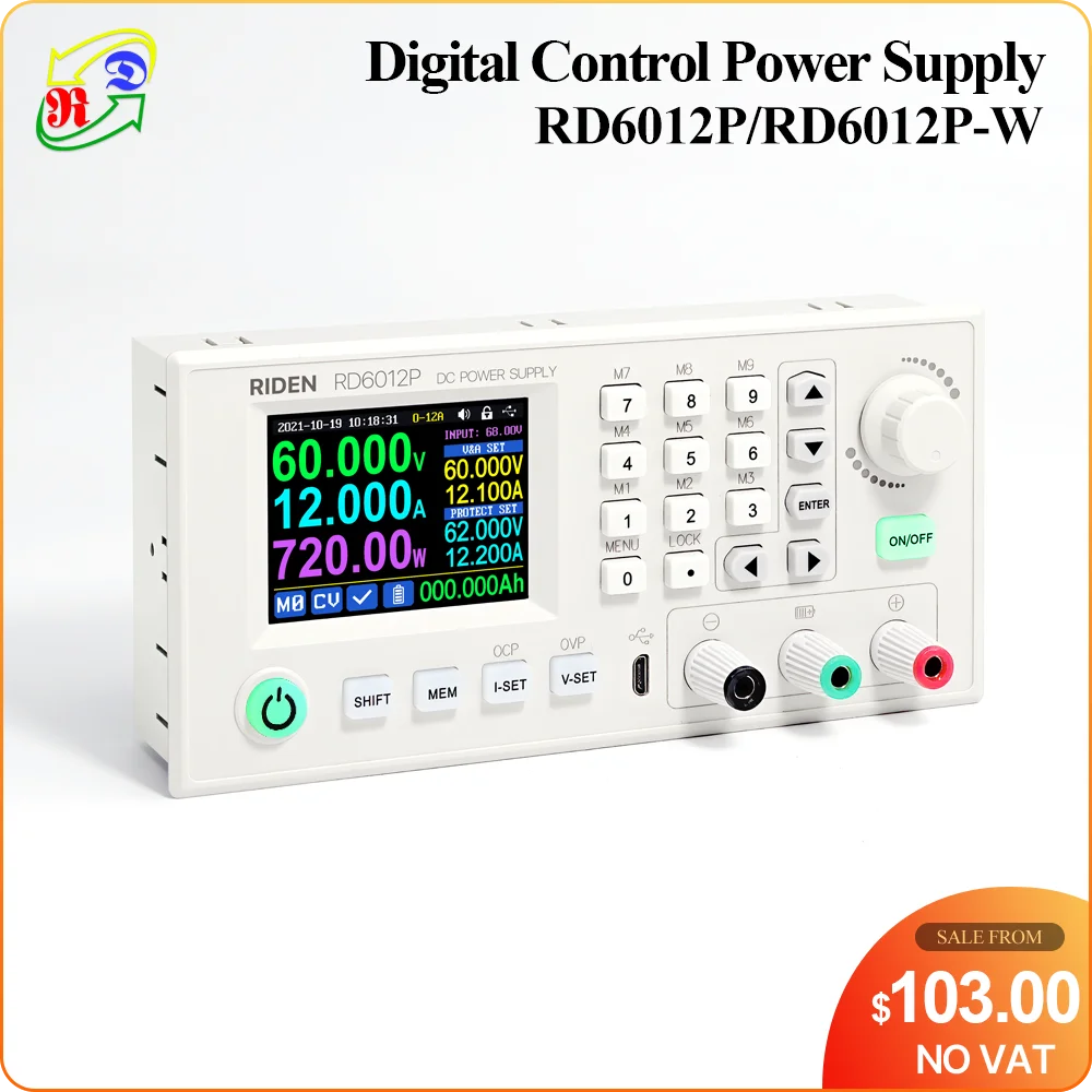
RD RD6012P RD6012PW USB WiFi 5 Digit DC to Voltage Step down Power Supply Adjustable buck converter voltmeter 60V 12A | Инструменты
История изменения цены
*Текущая стоимость 4 560,32 - 10 753,71 уже могла изменится. Что бы узнать актуальную цену и проверить наличие товара, нажмите "Добавить в корзину"
| Месяц | Минимальная цена | Макс. стоимость | Цена |
|---|---|---|---|
| Sep-18-2025 | 5426.83 руб. | 5697.17 руб. | 5561.5 руб. |
| Aug-18-2025 | 5381.77 руб. | 5650.32 руб. | 5515.5 руб. |
| Jul-18-2025 | 4514.72 руб. | 4740.80 руб. | 4627 руб. |
| Jun-18-2025 | 5290.1 руб. | 5555.83 руб. | 5422.5 руб. |
| May-18-2025 | 4606.17 руб. | 4836.60 руб. | 4721 руб. |
| Apr-18-2025 | 5198.13 руб. | 5458.1 руб. | 5328 руб. |
| Mar-18-2025 | 5153.52 руб. | 5411.18 руб. | 5282 руб. |
| Feb-18-2025 | 5107.47 руб. | 5362.26 руб. | 5234.5 руб. |
| Jan-18-2025 | 5062.13 руб. | 5315.56 руб. | 5188.5 руб. |
Описание товара


NOTE for Switching power supply: When get the PSU, please use multimeter to check if the real output voltage is stable and fits the rated voltage, to see if it is damaged on the way, if the output is abnormal, please contact us, do not connect it to RD power supply to avoid more loss
For some countries, you can get RD6006W/RD6012W/RD6018W whole set in this link with free faster express: www.aliexpress.com/item/1005002058172206.html

If you need the output cables, you can check the picture above:

All RD6012P/RD6012PW instruction and case installation instruction download Link :
1, RD6012P(W) operation instructon, PC software instruction , APP instruction ,APP and PC software download link:
A: Main download llink : //drive.google.com/drive/folders/1NdHp_BiQKGyVf5ahfyhNrGkTcO2AzWC0?usp=sharing
2,Android APP: download at file link:
, Support android 5.0 -android 10.0
IOS APP download: Search RdPower to download , support IOS10.0-IOS13.4 System
Android APP Google Playdownload:Search RdPower to download , support Android 5.0 and above phone
3,RD6012P and S800 case assemble instruction :
//drive.google.com/drive/folders/1NdHp_BiQKGyVf5ahfyhNrGkTcO2AzWC0?usp=sharing
Note before buying:
1,RD6012P series has two versions:RD6012P and RD6012P-W,RD6012P-W have WIFI board , RD6012P don't have . RD6012P-W can use WIFI board to connect APP, also use USB micro cable to connect PC solftware . RD6012P don't have WIFI board, only support PC software by connecting with USB micro cable, no support APP. For wifi board to connect PC software, now it did not support.
Note: WiFi connection is a test function, due to poor compatibility of some computers, if you cannot connect PC software via WiFi, please ignore this function. Forthis function, we do not provide any guarantee and technical support, and we will decide whether to keep this function based on customer feedback.2, for PC software, it only support win 7 and above for now. For APP, it only support android 5.0 and above.For APP and PC software, because there may be incompatibilities problems, please download first before buying , if you can download and install, you can make order, or else stop buying. If you don't test the PC software and APP function before buying and find that the products works fine except the PC software or APP, we refuse to refund.
3,S800 case is only case, not containing any power supply. some picture show installation finished by RD6012P , switch power and case .
For S800 case, it is just case, not conntaining any power supply, but it is suitable for RD6012P/RD6012PW and AC-DC 800W switching power supply, you can buy them seperately to assemble .
4,if you connect inductive load (such as motor), the max working current is 1/3 of range. don't exceed it.
S800 assembly video:www.youtube.com/watch?v=L_90NVUbb3M

4, for input AC-DC switch power supply, we recommend 800W switch power supply (S800 case leave fix hole size for this version),you can see more parameters about the800W switch power supply:

Note for input PSU
1.friendly reminder
If you do not order the whole set, the device can only be powered with DC input, no AC input. You need to use switching power supply for AC input, and it must be grounded, otherwise there is a risk of leakage
2.Recommend PSU:
It is recommended to use our custom PSU or famous brand PSU!
3.Not recommended PSU
If you use AC-DC converter or transformer to power on RD power supply, you must add rectifier and filter, DC output voltage without load should be lower than 65V,power grid voltage fluctuation will cause the high output voltage and burn the device!
4.Banned PSU
Forbid using electric bike charger, second-hand power supply, modified power supply, especially the PSU that claims to be suitable for RD power supply but we have not recommended ......These devices output are extremely unstable and may output high voltages and burn your load!
(bad PSU will have peak overvoltage)

there may be scratches on the surface but it doesn't affect the product performance, please do not be over picky, and if you do mind this, please do not buy this product

5,for S800 case, durning the shipping,maybethe case side wiil be a littledeformation (just like picture), you can use your hand to adjust, that's ok, if you mind this , please stop buying.


6,we show some data you want to see about RD6012P, dual current range, output accuracy, output ripple, full output test: //youtu.be/euPu_lzJ6dw
8.If RD6012PW can connect to the hotspot shared by the mobile phone but cannot connect to the router, you need to shut down the client isolation/ AP isolation and WMM function.
9.install the device in the right way

Friendly reminder:
·there may be high-frequency noise when the 800W 65V switch power supply is powered on and there is no load, which can be improved by adding a load resistoras shown in the figure! But for some people, they can still hear the noise, if you mind the noise, please do not buy this power supply, 800W 68V version does not need it·You can only connect the cables with a foundation in electronic and electrical engineering and it must be reliably grounded!·Due to express delivery, some power supply warranty labels may be damaged, which does not affect product warranty!·Due to the different power supply production batches, the internal material details may be different, hereby explain!
10.There is a BACKUP fuse in the RD6012P/RD6012PW box, if you burn the fuse, you can insert the fuse in the socket next to the burned one for temporary use, but the socket can only support under 10A for short time usage, so it is better to remove the damaged fuse and solder the good fuse on the same position
11.when intall our 800W PSU into our case, please follow our instruction to assemble, do not remove the shell of the PSU to use. After the shell of the switching power supply is removed, the structural change of the heat dissipation system will lead to insufficient heat dissipation,and some components will be overheated and damaged, in this case we don't offer after sell service

Instruction video for manual(similar to RD6006):
a.Battery Charging Function Introduction://youtu.be/irTbqfqtgU0
b.Output Voltage and Output Current Setting://youtu.be/S6Kan66dNsk
c.Data Group Quick Storage and Call out://youtu.be/eo5saPjOGpo
d.Keypad lock and unlock://youtu.be/zxpmasJyQ6Y
e.System Setting://youtu.be/Q9d3rIgIrOc
f.Main Page Style Setting://youtu.be/f51VDiY2VHE
g:Storage Data Setting://youtu.be/i1kTeurS13I
h:System Information://youtu.be/Um4NQObeeJE
i:IOS APP Download, Installation and Connection://youtu.be/nH2HYwop0TE
j:IOS APP Operation://youtu.be/lXSw1CM9IY8
k:Android APP Download, Installation and Connection://youtu.be/QwyBEUCnp9c
l:Anroid APP Operation://youtu.be/hqrF4keTfbE
m:PC Software Download and basic operation://youtu.be/mjt1RMaah1Y
o:Firmware Upgrade://youtu.be/NOoLfDw0DiY
p:Calibration://youtu.be/c9sn1wY2mjE
q:Logo Update://youtu.be/vuVhBsohWts
r: RD6012 wifi connection Problem and solution://www.youtube.com/watch?v=7sTtc1kweJM

Affected by the injection molding process, there are slight traces at the button holes of the shell. It can hardly be found in normal use. It can be found under the light (the shell is not crafts, don't be overly picky). as shown in picture 1,if you care, please don't buy this product
Technical parameters
Model | RD6006(W) | RD6012(W) | RD6018(W) | RD6006P(W) | RD6012P(W) |
Input voltage range | 6-70.00V | 7-70.00V | |||
Output voltage range | 0-60V | ||||
Output current range | 0-6.000A | 0-12.00A | 0-18.00A | 0-6.0000A | 0-12.000A/ 0-6.0000A |
Output power range | 0-360W | 0-720W | 0-1080W | 0-360W | 0-720W |
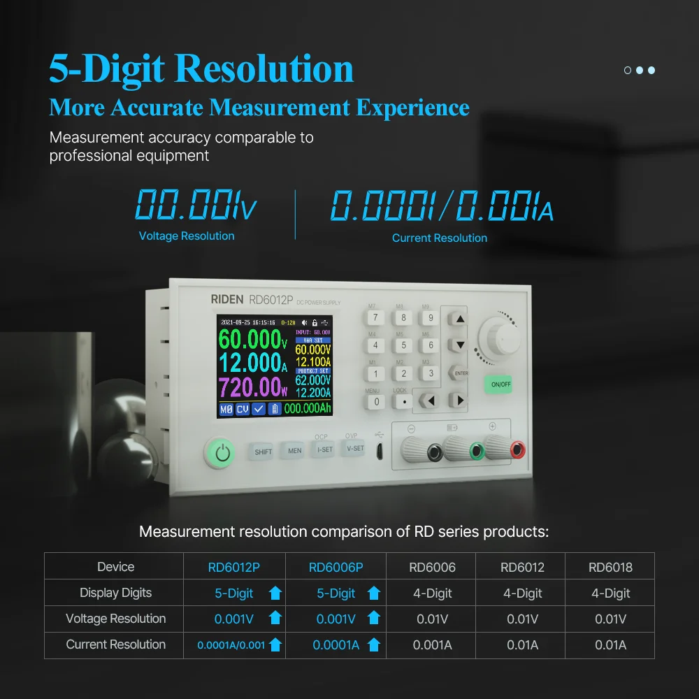
Input voltage measurement resolution | 0.01V | ||||
Output voltage setting measurement resolution | 0.01V | 0.001V | |||
Output current setting measurement resolution | 0.001A | 0.01A | 0.0001A | 0.001A/ 0.0001A | |
Battery voltage measurement resolution | 0.01V | ||||
Input voltage measurement accuracy | ±(1%+5 digits) | ||||
Output voltage accuracybetween setting and measurement | ±(0.3%+3 digits) | ±(0.5‰+4digits) | |||
Output current accuracy between setting and measurement | ±(0.5%+5 digits) | ±(1‰+6digits) | |||
Battery voltage measurement accuracy | ±(0.5%+3 digits) | ||||
Automatic cut off currentvaluewhen charging | 10mA | 100mA | Set by yourself | ||
Output ripple typical | 100mV VPP | 250mV VPP@6A | 20mV VPP① | ||
Working temperature range | -10℃~40℃ | ||||
External sensor Temperature detection range: | -10℃~100℃/0℉~200℉ | ||||
External sensor Temperature detection accuracy: | ±3℃/±6℉ | ||||
Constant voltage moderesponse time | 2ms(0.1A-5Aload) | ||||
Constant voltage mode load regulation | ±(0.1%+2 digits) | ||||
Constant current mode load regulation | ±(0.1%+3digits) | ||||
Capacity measurement range | 0-9999.99Ah | ||||
Energy measurement range | 0-9999.99Wh | ||||
Capacity and energy statistical error | ±2% | ||||
Buckworkingmode | Voltage drop>1Vand>10% | (input voltage÷1.1)-2② | |||
Cooling fan start condition | Output voltage>40VorOutput current>4Aor System temperature>45℃ | Output current>8Aor System temperature>45℃ | Output current >4A or System temperature>45℃ | Output current>4A or System temperature>50℃ | |
Cooling fan shut down condition when working | Output voltage<40VandOutput current<3.9Aand System temperature<45℃ | Output current<7.9Aand System temperature<45℃ | Output current <3.9A and System temperature <45℃ | Output current <3.9A and System temperature <50℃ | |
Over temperature protection | System temperature >80℃ | ||||
Screen brightness setting | 0-5(6 level in total) | ||||
Screen | 2.4inch color HD display | ||||
Weight(with package) | About 0.58kg | About 0.61kg | About 0.68kg | About 0.62kg | About 0.66Kg |
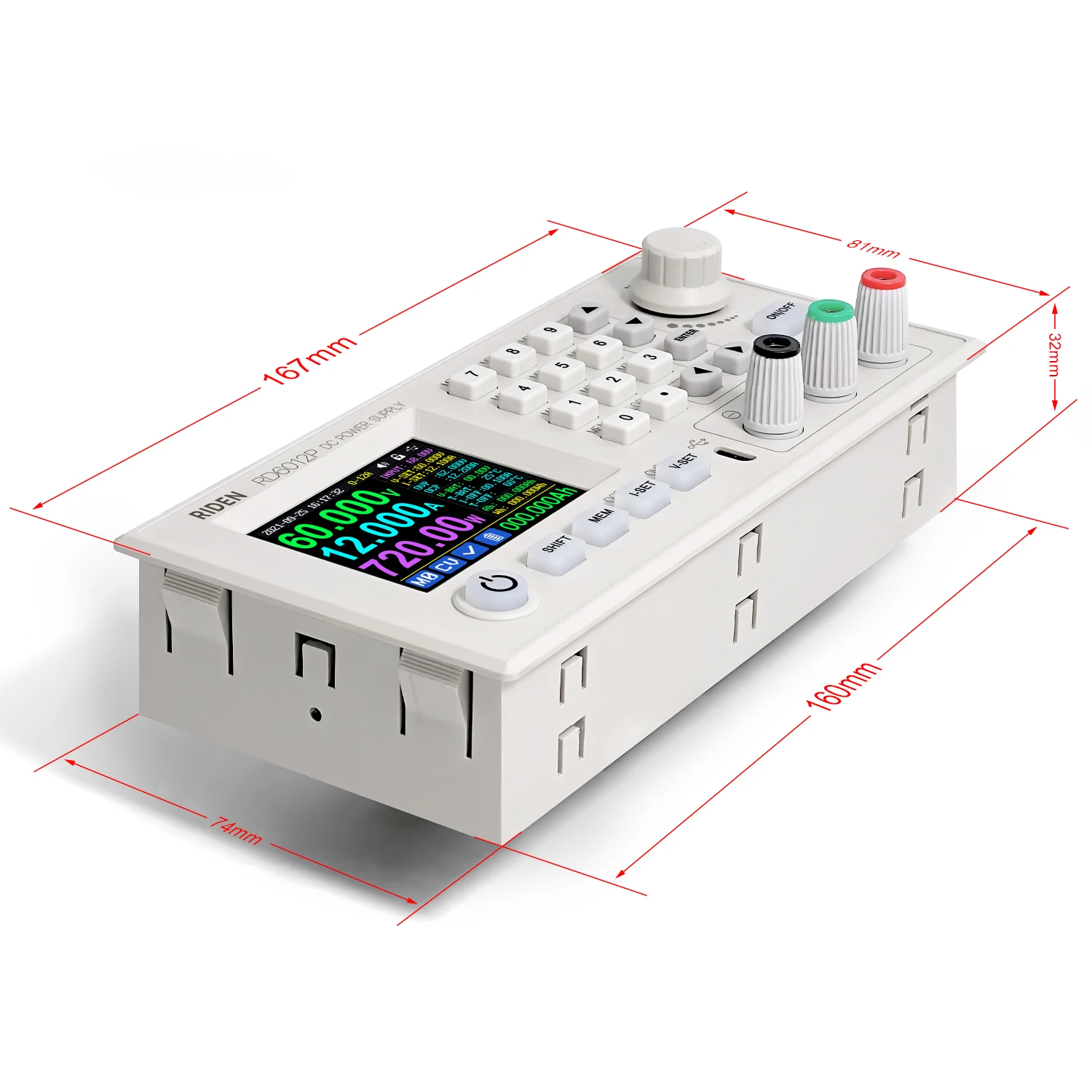
Product dimension | 167*81*65mm | 167*81*69mm | 167*81*65mm | ||
Support USB communication | Yes | ||||
Support WiFi communication | Only for RD60XX-W version | ||||
①:Ripple measurement method: noise and ripple are measured at X1 range, AC coupling,
20MHz of bandwidth on your oscilloscope with a 0.1uF parallel capacitor at the output terminals
②for example: input voltage is 24V,the max output voltage is 19.8V.


DC Power Supply Instruction
Model: RD6012P/ RD6012P-W
Date:2021.10.26
Dear users, thank you for purchasing the constant voltage constant current DC power supply produced by Hangzhou Ruideng Technology Co., Ltd. In order to let you know more about the full function of this product, get a better experience and avoid misuse. Please read this instruction carefully before using it. Keep it for future reference.
Note: This instruction is corresponding to firmware V1.38, the page and operation may be different under different firmware versions, please pay attention when using it. We do recommend you to download the latest firmware for better experience.
1.2 Core Function
Keypad + encoder potentiometer combination adjustment
·10 data groups for storage and call out
·2.4 inch HD color display
·Dedicatedterminal for battery charging
·Firmware update, support more functions later
·Brand new PC software
·Support WiFi communication(RD6012P-W) /USB communication
·Support Android/ IOS APP
·Support multiple display interfaces
1.3 Panel Instruction
1.3.1 Front Panel

A: Power button | B: SHIFT Second function button |
C: Quick storage button | D: Current/Over current protection setting |
E: Voltage/Over voltage protection setting | F: Micro USB port |
G: Power supply output negative terminal/ Battery charging negative terminal | H: Battery charging positive terminal (Dedicated terminal for battery charging) |
I: Power supply output positive terminal | J: Output switch |
K: Enter/Confirm button | L: encoder potentiometer/Cancel button |
M:Direction button | N: keypad |
O: Screen |
1.3.2 Back Panel

P: Input fuse | Q: Output fuse(only for under 10A short time usage) |
R: Power source input interface | S: External temperature sensor interface |
T: CR1220 battery socket | U: Communication module interface( wifi or RS485 board) |
V: Fan interface(cannot add or replace other fan) | |
NOTE:
Power source input interface must be connected to 7-70V constant DC power source. When the input voltage is greater than 72V, the output will be automatically turned off and an alarm (as shown in the right picture) will be automatically prompt. When the input voltage exceeds more, the product will be directly damaged and cannot be repaired!

The external sensor cable must be connected to the external temperature sensor interface. The fan interface cannot be connected to other fans. When the system temperature is higher than 80℃, the output will be shut down and show OTP on the screen. CR1220 is the clock battery (Please prepare by yourself), it can power on the clock function. Communication interface is a special interface, please don’t connect to other modules or cables.
You can see the Wi-Fi module and RS-485 module in the picture below. If you need RS-485 for industrial batch test and it is not on sale now, if you want to use that, please contact us.
1.4 Operation Instruction
After power-on, it will show boot image first, and then enters the main page.
1.4.1 Main Page
![]()

AA: Actual output voltagevalue | AB: Actual output currentvalue | |
AC: Output power | AD: Current data group | |
AE: Constant voltage Constant current status | AF: Protection status indication | |
AG: Battery charging indication | AH: Battery related information display area | |
AI: Over current protection value | AJ: Over voltage protection value | |
AK: Output current preset value | AL: Output voltage preset value | |
AM: Input voltage | AN: Communication interface | |
AO: Button lock status | AP: Button tune | |
AQ: Current range | AR: Date time |
|
|
|
Traditional Style | Detail Style | Curve Style |


At main page you can press ![]()
![]() button to change the display style between Traditional Style, Detail Style and Curve Style, the display style will not be saved automatically, you need to set default boot display at section 1.4.2.6 Main Page Style Setting.
button to change the display style between Traditional Style, Detail Style and Curve Style, the display style will not be saved automatically, you need to set default boot display at section 1.4.2.6 Main Page Style Setting.
1.4.2 Operation Introduction
In the menu operation, the icon in red or cursor is the currently selected menu, press ![]() to confirmor enter, press the encoder potentiometer to cancel or return, press the direction button to move the cursor or switch menu, rotate the encoder potentiometer to change the setting, the settings will be automatically saved when returning from the menu page. Press and hold the 0 button and power on to restore the factory settings, press and hold the 1 button and power on to restore the factory calibration value, press and hold
to confirmor enter, press the encoder potentiometer to cancel or return, press the direction button to move the cursor or switch menu, rotate the encoder potentiometer to change the setting, the settings will be automatically saved when returning from the menu page. Press and hold the 0 button and power on to restore the factory settings, press and hold the 1 button and power on to restore the factory calibration value, press and hold ![]() and power on to enter the boot mode.
and power on to enter the boot mode.
1.4.2.1 Battery Charging Function Introduction
Battery charging operation video:
//drive.google.com/drive/folders/1g8v_l1X9uwRM1P4GPwKhnP4NopKIUm1s?usp=sharing
After poweron,at battery related information display area, external temperature, capacity and energy will loop display. When theoutput is turned on:capacity, energy will be automatically accumulated, and automatically cleared after power off.
The green terminal is connected to the positive electrode of the battery, and the black terminal is connected to the negative electrode of the battery. After the battery is correctly connected, the battery charging indicator turns red ![]() and the battery is connected. Press
and the battery is connected. Press ![]() to start charging, the battery charging indicator turns green
to start charging, the battery charging indicator turns green ![]() . When the actual output current is lower than cut off current value (10 mA, can be set by user),or the temperature that the external temperature sensor tested is greater than the cut off temperature value, the output will be cut off automatically. Battery with protection board needs to be charged with red and black terminals. The charging voltage and current should be set on your own.
. When the actual output current is lower than cut off current value (10 mA, can be set by user),or the temperature that the external temperature sensor tested is greater than the cut off temperature value, the output will be cut off automatically. Battery with protection board needs to be charged with red and black terminals. The charging voltage and current should be set on your own.
It is strongly recommended to use the original charger to charge the battery. The charging function of this machine can only serve as a temporary replacement, not for long-term use. You need to know the battery parameter well so that you can use it to charge, There is a risk of fire and explosion during the charging processif you use the wrong way to charge.
1.4.2.2 Main Page Output Voltage and Current Setting
Output voltage and current setting operation video:
//drive.google.com/drive/folders/1NZW7k3-Kyc5YgIh-bWn8gBGaY5xo7_Lm?usp=sharing
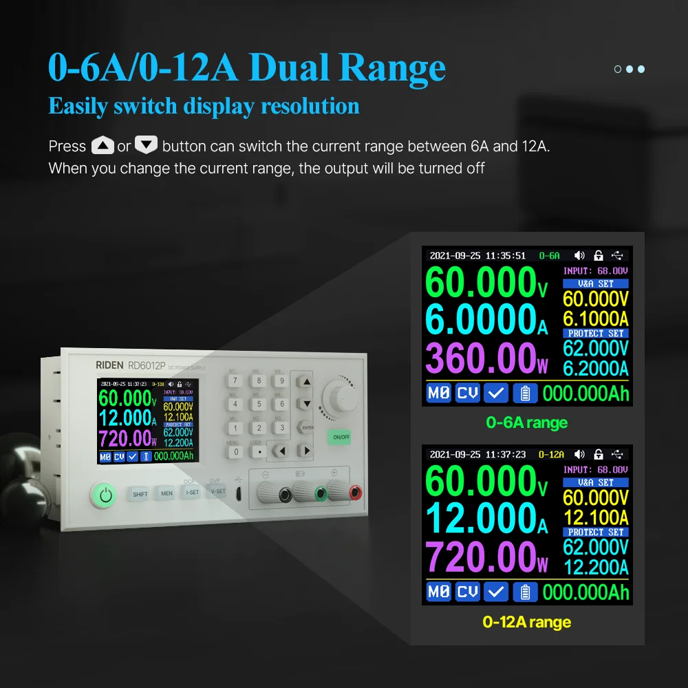
Press ![]() or
or ![]() button can switch the current range between 6A and 12A.When you change the current range, the output will be turned off
button can switch the current range between 6A and 12A.When you change the current range, the output will be turned off
|
Figure1 |


Press ![]() button to set the output current value, you can use encoder potentiometer to adjust the output value directly. And you will not set the value which exceeds the limit in this way, press
button to set the output current value, you can use encoder potentiometer to adjust the output value directly. And you will not set the value which exceeds the limit in this way, press![]()
![]() button to move the cursor. Of course you can use keypad to type in the value, and press
button to move the cursor. Of course you can use keypad to type in the value, and press ![]() to confirm, and it will save the set value and set current range, if you set a value exceeds the limit, it will prompt like what shows in Figure 1. If you set the wrong value, you can press encoder potentiometer to cancel.
to confirm, and it will save the set value and set current range, if you set a value exceeds the limit, it will prompt like what shows in Figure 1. If you set the wrong value, you can press encoder potentiometer to cancel.
Press ![]() button to set the output voltage value, the operation way is similar to output current setting.
button to set the output voltage value, the operation way is similar to output current setting.
Press ![]() +
+![]() button /
button / ![]() +
+ ![]() button to set the over current protection/ over voltage protection value. The operation method is similar to output current setting.If you want to set the over current auto cut off function, your OCP value should be higher than the Current setting value.
button to set the over current protection/ over voltage protection value. The operation method is similar to output current setting.If you want to set the over current auto cut off function, your OCP value should be higher than the Current setting value.
When the device is under constant voltage mode, it will show ![]() , and it will show
, and it will show ![]() when under constant current mode; when the device works normally it will show
when under constant current mode; when the device works normally it will show ![]() at protection status indication, when the actual output current value is higher than the over current protection value(OCP), the output will be cut off automatically, and show
at protection status indication, when the actual output current value is higher than the over current protection value(OCP), the output will be cut off automatically, and show ![]() , when the actual output voltage value is higher than the over voltage protection value(OVP), the output will be cut off automatically, and show
, when the actual output voltage value is higher than the over voltage protection value(OVP), the output will be cut off automatically, and show ![]() , when the system temperature is higher than 80℃, the output will be cut off automatically, and show
, when the system temperature is higher than 80℃, the output will be cut off automatically, and show ![]() .
.
1.4.2.3Data Group Quick Storage and Call out
Data group quick store and call out operation video:
//drive.google.com/drive/folders/139d28IHpZEgpNEC6pfBVruNF3b9FRVWW?usp=sharing
Press ![]() + keypad button 1-9, you can store the output voltage value, output current value, over voltage protection value, over current protection value into the corresponding data group(as shown in figure 2).
+ keypad button 1-9, you can store the output voltage value, output current value, over voltage protection value, over current protection value into the corresponding data group(as shown in figure 2).
|
figure 2 |

then press ![]() to confirm, it will show
to confirm, it will show ![]() at bottom left, you can press
at bottom left, you can press ![]() button and choose “X”, then press ENTER to cancel, after change the setting value it will show
button and choose “X”, then press ENTER to cancel, after change the setting value it will show ![]() .
.
Press ![]() + keypad button 1-9 to quick call out the saved data (as shown above in figure 3) from the corresponding data group. Press
+ keypad button 1-9 to quick call out the saved data (as shown above in figure 3) from the corresponding data group. Press ![]() to confirm, It will show
to confirm, It will show ![]() ,
,
|
figure 3 |

after change the setting value it will show ![]() . When disable the “Take OK” option, it will be called out directly to change the data setting value, no prompt.
. When disable the “Take OK” option, it will be called out directly to change the data setting value, no prompt.
![]() is the default data group, when you edit the settings and press
is the default data group, when you edit the settings and press ![]() button or rotate encoder potentiometer to change the setting and press encoder potentiometer to return, it will be stored into
button or rotate encoder potentiometer to change the setting and press encoder potentiometer to return, it will be stored into ![]() automatically, or you go to the data group setting menu, change the setting and press encoder potentiometer to return, it will save too, and it will not save by other settings.
automatically, or you go to the data group setting menu, change the setting and press encoder potentiometer to return, it will save too, and it will not save by other settings.
1.4.2.4Keypad lock and unlock
Keypad lock operation video:
|
figure 4 |

//drive.google.com/drive/folders/121yIfNLh3O99AU4tUkxtC5q34XT3snn1?usp=sharing
Press ![]() +
+![]() to lock or unlock the keyboard. And the keypad will be automatically locked when communication starts, there will be
to lock or unlock the keyboard. And the keypad will be automatically locked when communication starts, there will be ![]() displayed on the top(cannot unlock manually),at this time, the power button can be used, pressing other button will show(as shown in figure 4), the keypad will be automatically unlocked after 3 seconds when the connection disconnected, there will be
displayed on the top(cannot unlock manually),at this time, the power button can be used, pressing other button will show(as shown in figure 4), the keypad will be automatically unlocked after 3 seconds when the connection disconnected, there will be ![]() displayed.
displayed.
1.4.2.5 System Setting
System setting operation video:
//drive.google.com/drive/folders/1JCPJkD92Iv2Qtplmd6rs1pQmajs1EsVB?usp=sharing
Press ![]() +
+ ![]() to enter thesystem setting menu,the icon in Red shows the menu being chosen, press
to enter thesystem setting menu,the icon in Red shows the menu being chosen, press ![]() or
or ![]() to enter the sub-menu,the option in blue is the option being chosen, you can rotate the encoder potentiometer to change setting, and you can press
to enter the sub-menu,the option in blue is the option being chosen, you can rotate the encoder potentiometer to change setting, and you can press ![]()
![]() button to select menu.
button to select menu.
Press ![]() +
+ ![]() to enter setting menu showed in figure 5, press
to enter setting menu showed in figure 5, press ![]() or
or ![]() to enter the sub-menu.
to enter the sub-menu.
|
figure 5 |

Settings Sub-menu:
System language is is set to English by default. You can also set Simplified Chinese, French, Germany and Russian language;
Take OK is set to ON by default, when you quickly call out a data group, there will be a prompt to let you confirm, if you set OFF for this option, the settings will be edited directly when call out a data group;
Take Out is set to OFF by default, when call out a data group, it will keep the previous output status, when set it ON, it will output directly when call out a data group.
Boot Power is set to OFF by default, when boot the device the output is cut off, when set it on, it will automatically turn on the output after booting.
Boot Logois set to ON by default, when boot the device, it will show the boot logo first, then enter the main interface, when set it OFF, it will enter the main interface directly.
Buzzeris set to ON by default,it will show ![]() on the top, and you can hear the beep when press the button. When set it OFF, it will show
on the top, and you can hear the beep when press the button. When set it OFF, it will show ![]() , there will not be beep when press the button.
, there will not be beep when press the button.
Backlight is set to level 4 by default, it can be set between level 0-5.
Update Rate is set to Low by default, you can set it low/mid/high, it is the fresh rate of the real output voltage and current.
Max Power is set to 740W by default, you can set it between 0-740W, it is the max output power. On the top you can see the *1 icon, it is the adjustment magnification, you can press ![]() or
or ![]() to choose the different magnification so that you can set the value quickly, The max output is default voltage priority mode, when the setting voltage*setting current is higher than the max power, the device will automatically
to choose the different magnification so that you can set the value quickly, The max output is default voltage priority mode, when the setting voltage*setting current is higher than the max power, the device will automatically
|
figure 6 |
|
figure 7 |
|
figure 8 |


decrease the output current setting value. When used together with low power power source, it is recommended to set the value as the rated power of the power source*95%;
Temperature unit is ℃ by default, it can be switched between ℃ and ℉(figure 6);
Battery Charger Sub-menu(figure 7):
CutOff Current is set to 10mA by default and it can be edited. On the top you can see the *1 icon, it is the adjustment magnification, you can press ![]() or
or ![]() to choose the different magnification so that you can set the value quickly, when the real output current is lower than this set value, the output will be cut off automatically.
to choose the different magnification so that you can set the value quickly, when the real output current is lower than this set value, the output will be cut off automatically.
Cut-Off Temp.is set to 60℃ by default, when the external temperature sensor detect over 60℃, the output will be cut off automatically.
Communication Sub-menu(figure 8):
Interface is set to USB by default, you can also set it to WIFI/TTL/RS485, USB means the micro USB port, you can see ![]() on the top when set it USB, and when the communication starts, it will show
on the top when set it USB, and when the communication starts, it will show ![]() ; You need to insert a WIFI board to use the WIFI function, and it will show
; You need to insert a WIFI board to use the WIFI function, and it will show ![]() on the top, and when the communication starts, it will show
on the top, and when the communication starts, it will show ![]() ; TTL is not available now; You need to insert RS485 module to use RS485, and it will show
; TTL is not available now; You need to insert RS485 module to use RS485, and it will show ![]() on the top, and when the communication starts, it will show
on the top, and when the communication starts, it will show ![]() .
.
Address is set to 001 by default, you can set it between 001 and 255;
The Baud rate and address on the device should be same with the information on PC software or APP. You can see more communication at PC software and APP section.
Date and Time Sub-Menu(figure 9):
Date and Time can be set from Year 2000 to 2100, press ![]() or
or ![]() you can select the option, and use encoder potentiometer can adjust the value, it will be applied immediately when you change the value, please do not set the wrong time
you can select the option, and use encoder potentiometer can adjust the value, it will be applied immediately when you change the value, please do not set the wrong time
|
figure 9 |
|
figure 10 |
|
figure 11 |
|
figure 12 |
|
figure 13 |


1.4.2.6 Main Page Display Style Setting
Main interface display style setting operation video:
//drive.google.com/drive/folders/1gMkuCZrr_G-PlyHqO-i6fxdS-XRvuOIG?usp=sharing
You can press ![]() +
+ ![]() to enter the system setting menu, then press
to enter the system setting menu, then press ![]() and it will be switched to display style menu(as shown in figure 10): you can press
and it will be switched to display style menu(as shown in figure 10): you can press ![]() or
or ![]() to enter the sub-menu.
to enter the sub-menu.
Layout Sub-menu:
Digits Style isset to Normal by default, you can set it to Normal/7-Seg V1/7-Seg V2(as shown in figure 11).
Home Style is set to 0(traditional style), you can also set it to 1(Detail Style) or 2(Curve Style), the display style you choose will become the default style after power on.
Custom Colors(figure 12):
You can set the the display colors for output voltage, output current, output power.....as shown in figure 10 and figure 11.After change the color, you need to turn on the Custom Colorsoption to apply the settings(as shown in figure 13).
1.4.2.7 Storage Data Setting
Data group setting in manual operation video:
//drive.google.com/drive/folders/13APYtlRAaMcKmStbWM8toB8oOW5wi4ph?usp=sharing
You can press ![]() +
+ ![]() to enter the system setting menu, and then press
to enter the system setting menu, and then press ![]() button twice to enter the data storage setting menu(as shown in figure 14).
button twice to enter the data storage setting menu(as shown in figure 14).
Press the Enter button to enter the sub-menu, press the direction button to choose the data group,you can rotate the encoder potentiometer to switch 6A and 12A range, then set the value.
Press ![]() button to set the output current value, you can use encoder potentiometer to adjust the output value directly. And you will not set the value which exceeds the limit in this way, press
button to set the output current value, you can use encoder potentiometer to adjust the output value directly. And you will not set the value which exceeds the limit in this way, press ![]() or
or ![]() button to move the cursor. Of course you can use keypad to type in the value, and press
button to move the cursor. Of course you can use keypad to type in the value, and press ![]() to confirm, and it will save the set value and set current range, if you set a value exceeds the limit, it will prompt like what shows in Figure 1. If you set the wrong value, you can press encoder potentiometer to cancel.
to confirm, and it will save the set value and set current range, if you set a value exceeds the limit, it will prompt like what shows in Figure 1. If you set the wrong value, you can press encoder potentiometer to cancel.
Press ![]() button to set the output voltage value, the operation way is similar to output current setting.
button to set the output voltage value, the operation way is similar to output current setting.
Press ![]() +
+ ![]() button /
button / ![]() +
+ ![]() button to set the over current protection/ over voltage protection value. The operation method is similar to output current setting.
button to set the over current protection/ over voltage protection value. The operation method is similar to output current setting.
After setting, press the encoder potentiometer to return and save setting.
|
figure 14 |

1.4.2.8 System Information
System information operation video:
//drive.google.com/drive/folders/1APFNHtOufuh46rc5i2XTZKrQoTqgHdUr?usp=sharing
You can press ![]() +
+ ![]() to enter the system setting menu, and then press
to enter the system setting menu, and then press ![]() button 3 times to enter the system information menu(as shown in figure 15).
button 3 times to enter the system information menu(as shown in figure 15).
Product Model is the device name, Product SN is product serial number, Firmware is the firmware version, Temperature is the System temperature.
|
figure 15 |

2.1 Mobile Phone APP Installation
Only RD6012P-W supports WIFI connection. This App only supports Android 5.0 to Android 10.0 operating system, and there may be incompatibilities problems between APP and operating system, please install and test the software before buying the product.It will apply for location service, please agree and turn on the location service. After downloading the mobile APP zip-file, please install the APP from file manager. Don’t install or remove Wi-Fi module when the powered on, otherwise it will be damaged.This instruction is made for version 1.0.9, there will be little difference between different versions, and we do recommend you to download the latest APP for better experience.
2.1.1 APP Download
You can download the APP in Google Play by searching “RDPower”.
You can also download the RD60XX APP zip-file in this URL:
//drive.google.com/drive/folders/1V0l6P1sIJilN1yBOsTO9YGLVdkuO0cX9?usp=sharing
If you cannot find the app in both ways, contact the seller to get it.
2.2 Installation Introduction
Android APP download and connection video instruction:
//drive.google.com/drive/folders/15GfqS3vN3prvdVYOT1_yGHjkz0jHk_LO?usp=sharing
2.2.1 APP Update
Click the APP icon, After the APP starts, it will automatically detect whether there is a new version, and it will remind you by popping the window.You need to check if there is a new version by manual detecting.If you download the APP from Google Play, you need to detect new version by yourself.
2.2.2 APP Interface Display
When finish the installation and succeed in connection, it will show the main page as shown in the picture below.


BA:sidebar | BQ: move the cursor to the left |
BB:add device | BR: move the cursor to the right |
BC: return | BS: setbutton |
BD: more options | BT: screen brightness |
BE: curve | BU: system temperature |
BF: actual output voltage | BV: sync time |
BG: actual output current | BW: data group quick call out |
BH: actual output power | BX: battery voltage |
BI:input voltage | BY: external sensor temperature detecting value |
BJ: preset voltage value | BZ: accumulated output capacity |
BK: preset current value | CA: accumulated output energy |
BL: ON/OFF button | CB: device |
BM: protection status indication | CC: device name |
BN: keypad lock indication | CD: product SN number |
BO: constant voltage/current status indicator | CE: product firmware version |
BP: adjust wheel |
2.2.3 APP Operation
2.2.3.1 Network Distribution
|
figure 16 |

Connect Wi-Fi for the first time, please insert the WiFi board to the right position, then power on RD6012P, you will see the blue LED blinks once. Set the communication interface to WIFI, restart RD6012P, then place the RD6012P and the mobile phone close to the 2.4G router (the mobile phone must also be under the same 2.4G network, and the router must disable the AP isolation functionand the WMM function).
RD6012P will wait for the phone to connect as shown in Picture 16. Press “BA”(add device) and choose “RD power series”, it will show like Picture 17, then enter the WiFi password and confirm you are using 2.4G network as shown in Picture 18. Press “INITIALIZATION”and wait10 seconds.
|
|
figure 17 | figure 18 |


RD6012P will obtain the IP address of your phone(figure19), if it shows right, confirm that “device display sever IP”, and click “Confirm”, wait 20s (figure20),APP show connection successful, RD6012P will start automatically, the network distribution success, return to the main page and click the connect in the “BB”.
|
Figure19 |

|
|
figure 20 | |


If the distribution network fails, please power off the module and re-operate in the same way (multiple networking failures you canwatch the video and try to use the hotspot of the mobile phone to test).If you use Huaweibrand phone, please turn off the random MAC address function.
3.2.3.2 Proper Wi-Fi Connection
When power on RD6012P, it will connect Wi-Fi first, and then detect if it can be connected to APP, and it may not be connectedsuccessfully if the phone is under screen-lock status or the APP is running at the background. If the IP address of the phone has changed, you need to press the ![]() button and then press
button and then press ![]() button to reset the net, repeat 3.2.3.1 operation.We suggest you to set a fixed
button to reset the net, repeat 3.2.3.1 operation.We suggest you to set a fixed
2.2.3.3 APP Operation
Android APP operation video:
//drive.google.com/drive/folders/1vyIktoZ2ACqg1gW1uw4ZBWh7f_awHRtK?usp=sharing
Click “BJ” to set the output voltage, and use the wheel “BP” to adjust the value, the “BQ”, “BR” to change the position of cursor, click “BS” to set the parameter. Click "SHARE" in“BD”to exports the voltage-current curve to excel file, up to 24 hours document can be recorded.
NOTE:
There are many kinds of Android phone, so the user interfaces maybe different on some brand phones or different scales of the same brand.
Application permission requirements, allow the necessary permissions when the APP is installed (allow background running, using Bluetooth, operation on the folder, reading the application list, etc.) and also set the permissions of the APP after installation: Allow background running, never shut down when lock screen, allow self-starting (it is used to prevent the system from forcibly exiting the APP when recording data), etc.
IOS APP Instruction
3.1 Mobile Phone APP Installation
Wifi connection only supported for RD6012P-W.
3.1.1 APP Download
Apple APP only supports IOS10.0-14.3, iphone6 and above models, search for "RDPower" in the Apple store to download. If you must use the software function, please pre-install the test first. To use the WiFi function of the software, you need to apply for location service. Please agree and turn on location in Settings-Privacy. This manual corresponds to the software version 1.1.12, it is recommended to upgrade to the latest software for a better user experience.
3.2 Installation and Operation
|
|
figure 21 | figure 22 |


When the software is started for the first time, the system may apply for positioning (as shown in Picture 21), select "Allow when using APP", and apply for data when the software is running (as shown in Picture 22), select "Wireless LAN and cellular mobile network".
Apple APP installation and connection process video:
//drive.google.com/drive/folders/1h6Dbqum3b8uy0Ph7yRd4xhGcx8vHsdCZ?usp=sharing
After the installation is complete, the mobile APP icon is shown in the figure on the right:

3.2.1 APP Update
You can get the latest software from the Apple Store. When the software is updated, you will be prompted to update the version.
3.2.2 UI Instruction
You can see the user interface as shown in Picture below.

DA:connect/disconnect | DO: system temperature |
DB: export data to mobile phone | DP: data group quick call out |
DC: data curve | DQ: sync time |
DD: actual output voltage | DR: battery voltage |
DE: actual output current | DS: external sensor temperature detecting value |
DF: actual output power | DT: accumulated output capacity |
DG: input voltagemeasurement value | DU: accumulated output power |
DH: preset voltage value | DV: model being connected |
DI: preset current value | DW: product SN number |
DJ: output ON/OFF button | DX: product firmware |
DK: protection status indication | DY: switch current range |
DL: battery status indication | DZ: main page |
DM: constant voltage/ constant current status | EA: network distributionpage |
DN: screen brightness | EB: control center |
3.2.3 APP Operation
3.2.3.1 Network Distribution
Connect Wi-Fi for the first time, please insert the WiFi board to the right place,
|
figure 23 |

then power on RD6012P, you will see the blue LED blinks once. Set the communication interface to WIFI, restart RD6012P, then place the RD6012P and the mobile phone close to the 2.4G router (the mobile phone must also be under the same 2.4G network, and the router must disable the AP isolation functionand the WMM function).
RD6012P will wait for the phone to connect as shown in figure23. Press “EA”to choose Network distribution, it will show like figure 24, then enter the WiFi password and click INITIALIZATION. Waitabout 20 seconds.
|
|
figure 24 | figure 25 |


RD6012P will obtain the IP address of your phone(figure26), if it shows right,
|
figure 26 |

confirm that “device displayssever IP”, and click “CONFIRM”, wait 30s (figure25),APP showsconnection successful, RD6012P will start automatically, the network distribution success, return to the main page and click “DA” to connect.
If the distribution network fails, please power off the module and re-operate in the same way (multiple networking failures you canwatch the video and try to use the hotspot of the mobile phone to test).
3.2.3.2 Proper Wi-Fi Connection
When power on RD6012P, it will connect Wi-Fi first, and then detect if it can be connected to APP, and it may not be connectedsuccessfully if the phone is under screen-lock status or the APP is running at the background. If the IP address of the phone has changed, you need to press the ![]() button and then press
button and then press ![]() button to reset the net, repeat 2.2.3.1 operation.
button to reset the net, repeat 2.2.3.1 operation.
3.2.3.3 APP Operation
IOS APP operation video:
//drive.google.com/drive/folders/1kwycXmbV_wkSYuT7KxuYsmXHV70KDyiq?usp=sharing
Click “DH”/ ”DI” text label and enter the valueto set the output voltage/ output current, then click at the blank area to return, if you enter a value exceeds the limit, it cannot be applied. Click “DB” to exports the voltage-current curve to excel file, up to 24 hours document can be recorded.
Click the “EB” personal center to set the software language or get help to use the APP.
PC Software Installation and Operation Instruction
Requirement: Win 7-Win10 system and the computer has Internet connection.
This PC software is designed by Hangzhou Ruideng technology CO., LTD, it has no virus, if your anti-virus software prompts for a virus warning, please allow all its features, otherwise it will affect the normal operation of the software.PC software supports Win7-Win10 system, and there may beincompatibilities problems, if you really need it, please install and test the software before buying the product. This instruction is made for version 1.0.0.9, there will be little difference between different versions, the version below does not support RD6012P. and we do recommend you to download the latest software for better experience.
RD6012P digital power supply file download link:
//drive.google.com/drive/folders/1nyd7W_JdeQhPLhKdgG_iCRQ3mHZenbIU?usp=sharing
4.1 Software Download
PC software download and basic operation video:
//drive.google.com/drive/folders/10Op21Q61xOzlPROqGrt0tuMTkzp00aQZ?usp=sharing
4.1.1 Unzip Files
The first time you use this software, you need to install the driver program first, you need to click CH341SER to install the driver, the insert a Micro USB cable into RD6012P and wait for the computer to install the driver.
4.1.2 Unzip Files
Unzip the file to Disk(D) of the PC. You need to run Net framework4.7.2.exe to install the .Net environment, then click RidenPowerSupply.exedirectly to use the software, please do not delete any files.


4.2.1 Software Connection
Double click RidenPowerSupply.exe to run the PC software.
Only RD6012P-W supports WiFi function, WiFi connection is a test function, due to poor compatibility with some computers, if you cannot connect PC software via WiFi, please ignore this function. For this function, we do not provide any guarantee and technical support,and we will decide whether to keep this function based on customer feedback.
WiFi connection video link:
//drive.google.com/drive/folders/1BZslMRSntMj9Se6hnsYANsv8XAVhIZZi?usp=sharing
Set the RD6012P communication interface to WiFi, and restart, RD6012P displays likefigure 27, click "WiFi Network" on the PC software to pop up the WIFI configuration interface (figure 29), click "Initialize" and wait for about 5 -10 seconds, after the RD6012P displays the local IP address (as shown in figure 28), click "Next" and enter the WiFi name and password, then click "Network distribution", wait for about 20 seconds, the PC software prompts that the connection is successful, and then Click "Connect".
|
figure 29 |

USB connection: Set RD6012P communication interface to USB and connect RD60012 and PC, the PC software prompts the serial port has been updated and licks “Connect”.
|
|
figure 27 | figure 28 |


4.2.2 PC Software Operation Instruction
Choose the right communication port, baud rate, slave address(default 001), click “CONNECT” to start communication. If the communication succeeds, the power supply button will be locked automatically, the buttons will automatically unlock after 3 seconds of accidental disconnection, and the “CONNECT” turns to “DISCONNECT”; Click “ON” to turn on the output of the power supply, and it will turn to “OFF”.

4.3 Functions Introduction
The PC software interface mainly has basic functions, firmware upgrade, Logo upgrade, version update detection and language setting...

FA: Voltage-Current Curve | FB: Battery information/ Data Group Quick Call Out |
FC: Calibration | FD: RD/DPS series switch |
FE: Language | FF: Software Update |
FG: About | FH: Input voltage |
FI: Actual Output Voltage | FJ: Actual Output Current |
FK: Actual Output Power | FL: System Temperature(℃) |
FM: System Temperature(℉) | FN: Constant Voltage/ Constant Current Status |
FO: Protection Status Indication | FP: Screen Brightness Setting |
FQ: Synchronize System Time | FR: Output Current Preset value |
FS: Output VoltagePreset value | FT: Firmware Version |
FU: Serial Number | FV: Product Model |
4.3.1 Basic Functions
PC software operation video:
//drive.google.com/drive/folders/1rl-CCOzbFlAONjRfrOpbNsK8rrCGVoKa?usp=sharing
The basic functions of PC software: voltage/current preset, data group quick call out, calibration fine tuning, brightness setting, voltage and current curve exporting. You can rotate the wheel or enter the value to set the voltage and current, the graph above the button shows the real-time voltage and current curve.You can zoom in and out the curve by using the mouse wheel, double click the curve to auto adjuststhe axis, you can right click on the curve to clean the curve or export the curve data to picture or excel.
4.3.2 Calibration
The calibration fine-tuning function needs to be operated by a professional electronic person who has more than Six and a halfdigit multimeter. It will change the system setting, incorrect operation may exceeds the hardware limit and cause damage, and the resulting damage is not covered in the warranty! The limit error of the product is generally much smaller than the nominal error, when the error is close to or even higher than the nominal error, you need to check if the measuring instrument is accurate.
RD6012P calibration operation video:
//drive.google.com/drive/folders/1WEusRYtpn94BFjyEQjrtsnzTo1K6hYcw?usp=sharing
Click “Calibration” and enter the password “168168”, you can enter the Calibration Fine Tuning pageor save the adjustment data(if you enter the password, by default you have accepted the above red letter agreement). It can read the calibration data after connection; click the arrow to fine tuning the data. According to the linear function y=kx+b, the constant b is equivalent to the zero value, the slope k is equivalent to the proportional value, adjust this two values so that the data will be close to the real test value.
Set the output voltage at 1V, adjust the output voltage zero point to make the multimeter display close to 1V, and then set the output voltage at 30V, adjust the output voltage proportional value to make the multimeter display close to 30V. In the same way you can set 0.1A and 3A output current to calibrate the zero point and proportional value of the output current.
Set the output voltage at 1V and calibrate the actual output voltage zero point to make the actual output voltage displayed on RD6012P close to the value on multimeter. You can set 30V and calibrate the proportional value of actual output voltage. In the same way you can set 0.1A and 3A to calibrate the zero point and proportional value of the actual output current.(This section does not provide technical support. If you do not understand, please check the related information).

4.3.3Advanced Function
You can set the output voltage and current by chart in the advanced function page, you can set every step between 1 and 9999 seconds, you can set 200 steps max, it can output automatically or manually. You cannot choose other operation page when it performs programming output or other operations, you can only switch other page when it ends.

4.3.4RS485 Multiple Devices Communication
For now RD6012P does not support RS485 module.
4.3.5 Firmware Update
Firmware update operation video:
//drive.google.com/drive/folders/19A8Rha_sWYuJ6nMGB7S9S7LuoNepe4by?usp=sharing
Press and hold ![]() and power on RD6012P, enter the boot mode, then connect it to computer, there will be “boot mode” in the mode information text box, then click “Firmware Update”, a firmware update prompt will pop up on the interface, and click “Now” to upgrade. (You can update the firmware under the normal mode, if it cannot be started up normally, you should press and hold the “ENTER” button and power on, update it under boot mode.It doesn’t support firmware update under WiFi connection mode).
and power on RD6012P, enter the boot mode, then connect it to computer, there will be “boot mode” in the mode information text box, then click “Firmware Update”, a firmware update prompt will pop up on the interface, and click “Now” to upgrade. (You can update the firmware under the normal mode, if it cannot be started up normally, you should press and hold the “ENTER” button and power on, update it under boot mode.It doesn’t support firmware update under WiFi connection mode).

During the firmware upgrade process, the interface is displayed as follows:

4.3.6 Boot Logo Update
Boot logo setting video:
//drive.google.com/drive/folders/1J0iOyxZ8DSJaDQD2xgrlukBwJBELQBzf?usp=sharing
Click “Start LogoUpdate”, a Logo upgrade prompt will pop up on the page, please select a picture. Some logo samples can be used in the installation package. Click “Picture Import” and RD6012P will reboot automatically.

4.3.7 Version Update Detection
Click“FF”(“Software Update”), the software will automatically detect if there is a new version, if so, an update prompt will pop up on the interface.

4.3.8 Language Setting
Click “Fe”(“Language”), a language setting prompt will pop up on the interface, you can choose Simplified Chinese, English, France and German.

4.3.9 About
Click “FG”(“About”), you can check the version number, publish time and copyright Information

Appendix
Appendix 1: Common Battery Voltage Comparison Table
Battery Type | Nominal Voltage (V) | Final Charge Voltage (V) | Final Discharge Voltage (V) | Application | Characteristics |
LiCoMnNiO2 | 3.7 | 4.2 | 3 | Digital Device | High capacity |
LiFePO4 | 3.2 | 3.65 | 2.5 | Electric bike/ electric tool | Large discharge current, inexpensive |
Lead Storage Battery | 12 | 14.4 | 10.5 | Car/ electric bike | Inexpensive Lead pollution |
Dry Battery | 1.5 | Cannot charge | 0.9 | Clock/Remote control | Inexpensive widely used not rechargeable |
NICD Battery | 1.25 | 1.5 | 1.1 | Toy | Inexpensive Memory effect |
Ni-MH Battery | 1.2 | 1.4 | 0.9 | Toy/Shaver | No memory effect |
Appendix 2: Common ElectricCar/BikeBattery Voltage Comparison Chart
Nominal Voltage | Battery Type | Number of batteries connected in series | Final Discharge Voltage(V) | Final Charge Voltage(V) |
48V | LiCoMnNiO2 | 14 | 42 | 58.8 |
LiCoMnNiO2 | 13 | 39 | 54.6 | |
LiFePO4 | 16 | 40 | 58.4 | |
Lead Storage Battery | 4 | 42 | 57.6 | |
36V | LiCoMnNiO2 | 10 | 30 | 42 |
LiFePO4 | 12 | 30 | 43.8 | |
Lead Storage Battery | 3 | 31.5 | 43.2 | |
24V | LiCoMnNiO2 | 7 | 21 | 29.4 |
LiFePO4 | 8 | 20 | 29.2 | |
Lead Storage Battery | 2 | 21 | 28.8 |
Note: if the final discharge voltage of the battery is higher than 60V, you cannot use RD6012P to charge, it will damage the device.
Смотрите так же другие товары: