

Новое поступление

Скандинавский обеденный стул из цельного дерева Кеннеди президент Хиросимы

refrigeration Series Hi-End-G Gold plated US Power Receptacles wall outlet distributor | Электроника
3 079,22 руб.

IYICAO классный розовый цветной мягкий черный силиконовый чехол для iPhone 11 Pro Xr Xs Max X

PIXIU милый узор телефон чехол для iPhone 6 6S 7 8 Plus X XR XS MAX Винни Медведь Свинья задняя

Комплект одежды для новорожденных мальчиков летние топы без рукавов с принтом

Белая футболка Vasco Non Stop Live 2019 |
847,06 - 1 562,03 руб.

Free Shipping !!Original D750 Main Board MCU MainBoard Mother MotherBoard For Nikon | Электроника
13 935,86 руб.
Характеристики
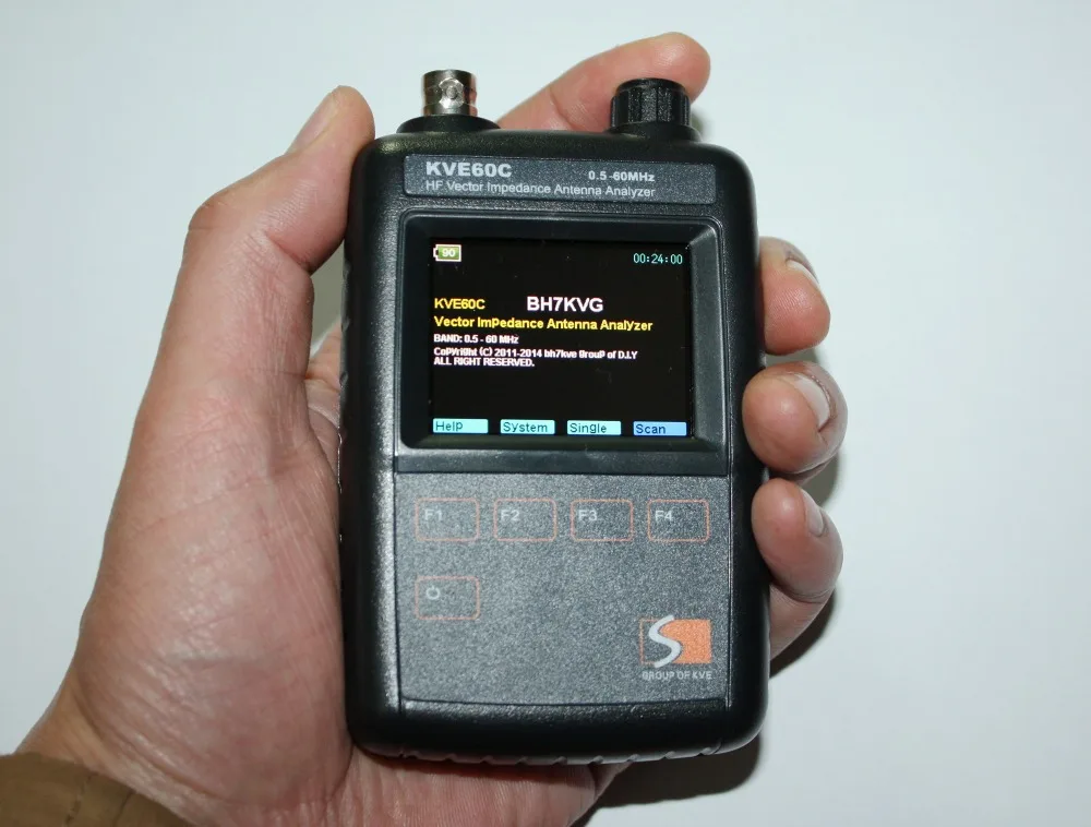
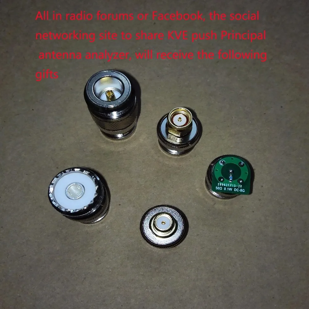
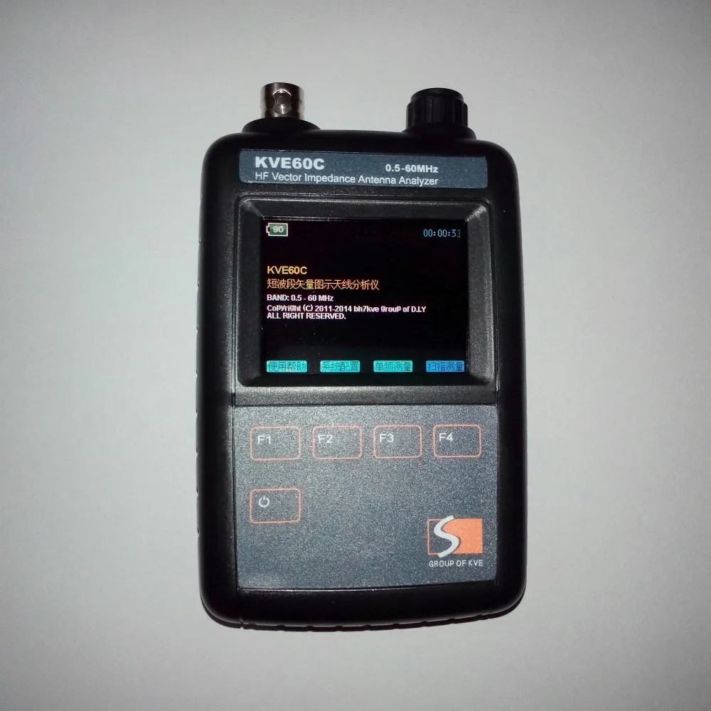
KVE-60C vector Antenna analyzer SWR HF Radio Amateur Color Graphic 0.5-60MHz Gift RF coaxial connectors + dummy load |
История изменения цены
*Текущая стоимость уже могла изменится. Что бы узнать актуальную цену и проверить наличие товара, нажмите "Добавить в корзину"
| Месяц | Минимальная цена | Макс. стоимость | Цена |
|---|---|---|---|
| Sep-18-2025 | 0.17 руб. | 0.31 руб. | 0 руб. |
| Aug-18-2025 | 0.63 руб. | 0.54 руб. | 0 руб. |
| Jul-18-2025 | 0.88 руб. | 0.69 руб. | 0 руб. |
| Jun-18-2025 | 0.20 руб. | 0.31 руб. | 0 руб. |
| May-18-2025 | 0.57 руб. | 0.50 руб. | 0 руб. |
| Apr-18-2025 | 0.61 руб. | 0.68 руб. | 0 руб. |
| Mar-18-2025 | 0.42 руб. | 0.96 руб. | 0 руб. |
| Feb-18-2025 | 0.7 руб. | 0.53 руб. | 0 руб. |
| Jan-18-2025 | 0.50 руб. | 0.55 руб. | 0 руб. |
Описание товара


Lasted more than a year
Nearly 1000 KVE-60 antenna analyzer HAM enthusiasm for participation
and feedback
After the test of time again upgrade will bring you more strong
feelings!
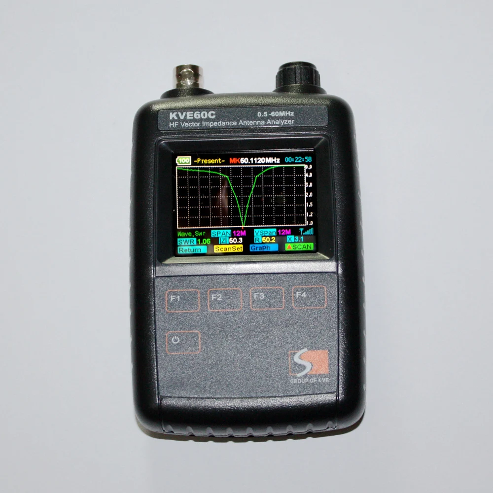
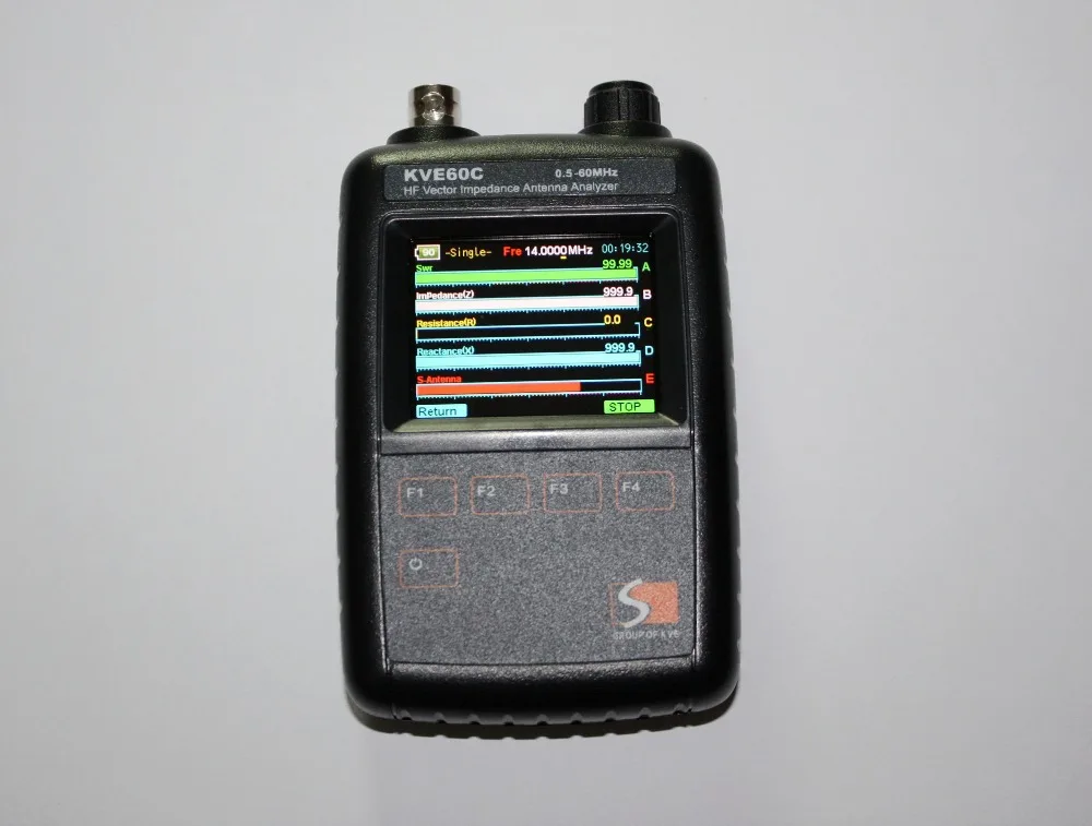
Picture is showing KVE60C is measuring 50Ohm shortwave antenna vector impedance. Where you can see, X (wave), SWR, R (resistance) and Z (complex impedance parameters)
To check and adjust the antenna resonance, and bandwidth matching.
KVE60C is requires users to have a certain radio basic theoretical knowledge in order to proper operating this device.
Specifications:
1 Display and protective glass: Sharp Transflective TFT, 1600 million color, QVGA. Mitsubishi hardened scratch resistant acrylic protective lenses.
2 VSWR 1.00-- - 99.99
3 Frequency range :0.5--60MHz
4 Frequency stability: <5PPM
5 Frequency Step: Min 100Hz / step
6 Output Level: 5dbm (based on 14MHz Test)
7 Scan width: 300K/600K/1.2M/2.4M/6M/12M/24M/48M
8 Scan Step: 1KHz/2KHz/4KHz/8KHz/20KHz/40KHz/80KHz/160KHz
9 impedance resistor reactance range :0.1---999.9 ohms
10 Power Supply: 3.7V 1800mAH lithium polymer (standard builtin)
11 Charging power supply: Micro USB standard connector (must ensure that the output voltage is DC 5.05.5V, and the current output capacity> 500mA)


12 Charge indicator: Hidden (when not charging)
(there are three instructions state: 1, charging (red) 2, charging is completed (green) 3, charging fault (flashing))
Charging Note:
Make sure the devide is fully charged, if it going to long idle. Check the power every 2 to 3
months.
If the battery is low, please promptly added to protect the lithium battery life.
Domestic users, we recommend using a large label smartphone charger, such as millet, Samsung, Nokia and other original charger.
Rechargeable lithium Tips:
When charging port, access to regular power supply (5V 500ma), a charge cycle begins, first check the battery voltage: If less than 2.9V, the charging circuit starts trickle charge mode (50ma charge current) charging.
When the lithium battery voltage rises above 2.9V, the charging circuit enters the constant current charging mode (500ma charging current).
When the battery voltage reaches 4.2V, the charging circuit enters constantvoltage mode (4.2V charge voltage), and the charge current begins to decrease, when the charging current is small to 50ma, stop charging, a charging cycle is completed.
Charging circuit enters standby mode. Even the full power state when the charging port, get new power supply, they would be a charge cycle.
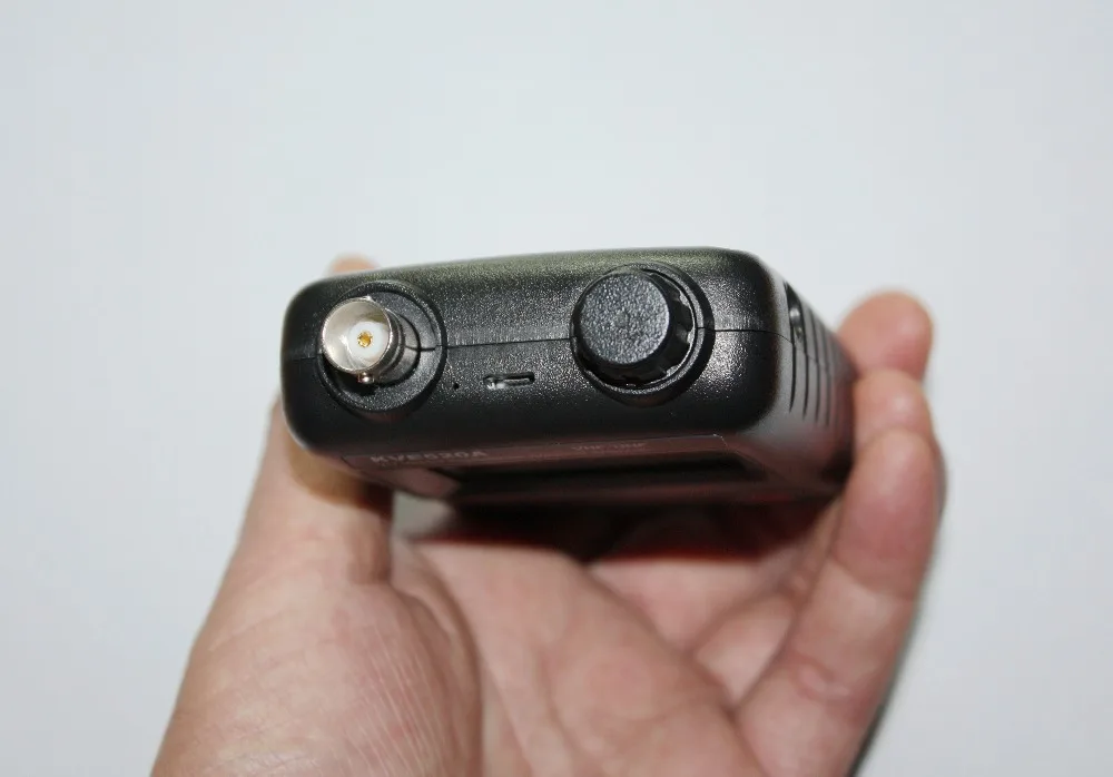
Hardware reset hole Note:
Although 60C operating system is very reliable and interference environment in large industrial applications, high frequency heating machine must be verified.
Hardware reset hole in the upper left side of the machine. In the case of strong interference cause system crashes encounter case.

You don’t need it (reset hole) in most of the case.
Basic Operations
Turn knobs and buttons Basic Operating Instructions
1, in the top of the device has a digital code can be rotated around the knobs, mainly used for frequency setting and query step to increase and decrease.

In VFO mode: Press the switch, adjust the frequency.
Press the switch 25 seconds to power on or power off the machine.
2, Picture at the bottom is showing four function keys.

3, In the lower right of the screen, antenna signal strength indicator on top of the SCAN. The scan operation is not displayed when the antenna field strength induced interference situation. When scanning, power output represents the measured excitation conditions.


4, on the Single scanning screen, there is a SAntenna signal strength indicator, which is a rough indicator of the antenna RF field.
Function with Scan screen, the same antenna signal strength indicator. Antenna Measurement Operation 1 (Scan mode):
1, in the start screen, press the SCAN button scanning measurement automatically entering
“Scan Set”

a, click on SPAN, select the appropriate SCAN bandwidth.
b, rotate the encoder potentiometer (potentiometer can be encoded by pressing the top switch to cycle through the input bits, bottom is showing input bit yellow indicator) select the frequency,

c, press the SCAN button to start the scan operation. During scaning, in order to ensure measurement accuracy, each frequency will stay for short while. one scanning cycle (300 collection points) will take about 23 seconds.
2, Once SCAN is done, it will enter ”Present” mode (result) screen (Note: Some versions of labeled:Result, meaning the same.)

You have 3 options: a, press the "Graph" icon mode button to switch curve shows the results of the scan mode, in addition to The SWR curve, there is the Z curve, R curve, X curve.


b, move the cursor, view the scan frequency point on the curve on each scan of the specific parameters of the measurement results.

c, move the cursor to view the results of the scan data in the process, you can press " "RUN" button to rescan from the current cursor position, if you need to change the bandwidth of a new scan, you can press the "Scan Set" key to enter the measurement setup screen, at this point the cursor will automatically move into the frequency parameter measurement screen, after settingScanSet(Scan Settings), press "SCAN" button to scan.)
Also returnPresent(Scan Results view, some revisions are labeled asResult) interface operation.
Scan data save and read:
When unit is shutdown, it will automatically save the last set of scan data into memory. Scenario::
When power on:
A, press the "Scan" (scanning) function selection key, enterScan Set(scan measurement setup) interface,
B, according to "Result" (Analysis) interface options to enterResult(Analysis) interface,
C, Press "Graph" (scan results curve) icon mode selection key, it will automatically transfer the stored scan data.
Antenna measurement operation 2 (single scan mode):
In the start screen: Press the "Single" singlefrequency mode measurement button, enter
Single (single scan mode) screen.

a, rotary encoder potentiometer enter the center frequency, the specific reference to the above operation "SCAN" sweep measurement mode descriptions.
b, press the ”RUN / Stop", to start and stop the scan.
Singlefrequency mode provides a single frequency impedance measurement, the measured frequency of the basic parameters are displayed on the screen. And to indicate the form of bars and numbers displayed on the screen quickly.
The scanning will not stop, until you press the Stop button.
In this mode, it can be used as an accurate signal generator, please refer to RF out.
ID callsign Input:
This function has nothing to do with scanning and testing.
1, in the boot screen, press the "system" to enterSystemuser interface (Figure ID1).
2, using the Select (Settings Select) button to select Callsign parameter settings (the name of the selected option will reverse display). (Figure ID2). Use the top coding switch operation callsign input:
a, selected character will be antisignificant bits, a total of eight characters can be input.
b, rotary coding switch can select: "", "/", '"09", "AZ" and other characters. The bits can be selected without using the space character '' character, will not be displayed.
c, if you do not want to use the boot interface Callsign display function, please call sign character is all set to blank space.
3, press Exit (Exit) key to exit the menu interface, return to the boot screen. This time the call sign is displayed in the boot interface. (Figure ID3)

ID1

ID2

ID3
The following shows the appearance of the product

Sale Description
Note: receipt inspection by Taobao rules, not otherwise specified. The
following content is the use of failure need aftermarket category.
Service time range:
A, the official version of the normal user purchase, the warranty to
the package to stop publishing a year.
B, the official version of the preferential purchase of user activity
to activity shall prevail.
C, internal beta purchase user to test the agreement shall prevail.
Service content:
In the meantime, the normal use, if failure occurs:
A, buyers pay shipping back and forth,
B, the seller charges the burden of maintenance and replacement
devices.
During this time buyers change, moving circuit devices, unconventional
use the package, if the fault occurs:
Buyer is responsible for return shipping costs and devices,
The seller is responsible for maintenance costs.
The following components are not in accordance with industry practice
Warranty:
Housing, LCD, battery, PCB (burned, flooding), the charger does not
warranty
Sellers can help buyers to replace.


Смотрите так же другие товары: