
IGBT Power Module FF600R17KF6-B2 FF600R17KF6C-B2 | Обустройство дома
50 915,16 руб.


Новое поступление
Характеристики
*Текущая стоимость US $155.00 уже могла изменится. Что бы узнать актуальную цену и проверить наличие товара, нажмите "Добавить в корзину"
| Месяц | Минимальная цена | Макс. стоимость | Цена |
|---|---|---|---|
| Aug-18-2025 | 197.76 руб. | 201.30 руб. | 199 руб. |
| Jul-18-2025 | 160.4 руб. | 163.54 руб. | 161.5 руб. |
| Jun-18-2025 | 194.68 руб. | 198.17 руб. | 196 руб. |
| May-18-2025 | 192.73 руб. | 196.81 руб. | 194 руб. |
| Apr-18-2025 | 153.48 руб. | 156.93 руб. | 154.5 руб. |
| Mar-18-2025 | 189.7 руб. | 193.10 руб. | 191 руб. |
| Feb-18-2025 | 188.21 руб. | 192.75 руб. | 190 руб. |
| Jan-18-2025 | 186.13 руб. | 190.54 руб. | 188 руб. |
Описание товара


The item will be shipped from Germany!
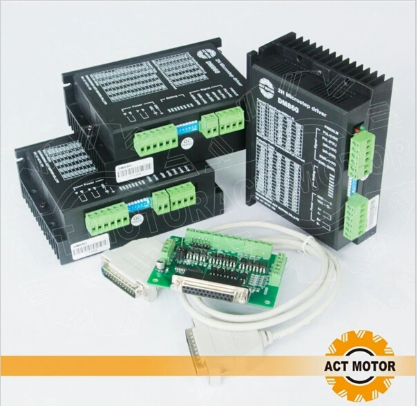
This package include:
3pcs stepper motor driver:M860
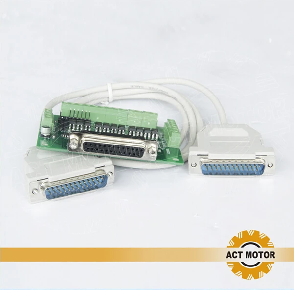
NOTE: 1PC 6AXIS breakout board for gift

Description
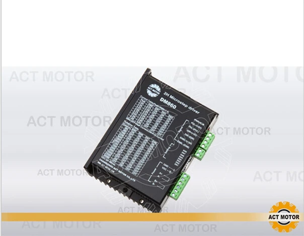
DM860 is a type of two-phase hybrid stepping motor driver, The drive voltage of which is from 24VDC to 80VDC. It is designed for use with 2-phase hybrid stepper motor of all kinds with 57mm to 110mm outside diameter and less than 7.8A phase current. This circuit that it adopts is similar to the circuit of servo control which enables the motor run smoothly almost without noise and vibration. Hording torque when DQ860MA run under high speed is also significantly higher than the other two-phase driver, what’s more, the positioning accuracy is also higher. It is widely used in middle and big size numerical control devices such as curving machine, CNC machine, and computer embroider machine, packing machines and so on.
Features: l High performance, low price l Average current control, 2-phase sinusoidal output current drive l Supply voltage from 24VDC to 80VDC l Opto-isolated signal I/O l Overvoltage, under voltage, overcorrect, phase short circuit protection l 14 channels subdivision and automatic idle-current reduction l 8 channels output phase current setting l Offline command input terminal l Motor torque is related with speed, but not related with step/revolution l High start speed l High hording torque under high speedElectrical specification:
| Pin Function | Details |
| PUL +,PUL- | Pulse signal, PUL+ is the positive end of pulses input pin PUL- is the negative end of pulse input pin |
| DIR+,DIR- | DIR signal: DIR+ is the positive end of direction input pin DIR- is the negative end of direction input pin |
| ENBL+ | Enable signal: ENBL+ is the positive end of direction input pin. This signal is used for enabling/disabling the driver. High level for enabling the driver and low level for disabling the driver. |
| ENBL- | ENBL- is the negative end of direction input pin. Usually left unconnected (enabled) |
2) Pins wiring diagram: PC’s control signals can be active in high and low electrical level. When the high electrical level is active, all control negative signals will be connected together to GND. When low electrical level is active, all control positive signals will be connected together to public port. Now give two examples( Open collector &PNP), please check them: Fig 1. Input port circuit (Yang connection) PC open connector output Fig. 2 Input port circuit ( Yin connection) PC PNP output Note: When VCC=5V, R=0 When VCC=12V, R=1K, >1/8W When VCC=24V, R=2K,>1/8W R must connect in the control signal part . 3.Function choice ( Using DIP pins to achieve this function) 1) Micro step resolution is set by SW 5,6,7,8 of the DIP switch as shown in the following table:
| SW5 | ON | OFF | ON | OFF | ON | OFF | ON | OFF | ON | OFF | ON | OFF | ON | OFF |
| SW6 | ON | ON | OFF | OFF | ON | ON | OFF | OFF | ON | ON | OFF | OFF | ON | ON |
| SW7 | ON | ON | ON | ON | OFF | OFF | OFF | OFF | ON | ON | ON | ON | OFF | OFF |
| SW8 | ON | ON | ON | ON | ON | ON | ON | ON | OFF | OFF | OFF | OFF | OFF | OFF |
| PULSE/REV | 400 | 800 | 1600 | 3200 | 6400 | 12800 | 25600 | 51200 | 1000 | 2000 | 5000 | 10000 | 25000 | 50000 |
| Output current (A) | ||||
| SW1 | SW2 | SW3 | PEAK | RMS |
| ON | ON | ON | 2.80 | 2.00 |
| OFF | ON | ON | 3.50 | 2.50 |
| ON | OFF | ON | 4.20 | 3.00 |
| OFF | OFF | ON | 4.90 | 3.50 |
| ON | ON | OFF | 5.70 | 4.00 |
| OFF | ON | OFF | 6.40 | 4.60 |
| ON | OFF | OFF | 7.00 | 5.00 |
| OFF | OFF | OFF | 7.80 | 5.60 |
| Motor and power pins | 1 | A+ | Motors wiring | |
| 2 | A- | |||
| 3 | B+ | |||
| 4 | B- | |||
| 5,6 | DC+ DC- | Power supply | Power supply :DC24-80VDC The peak input current can not up to 6A |
| Alarm indicator | Reasons | Measures |
| LED off turn | Wrong connection for power | Check wiring of power |
| Low-voltages for power | Enlarge voltage of power | |
| Motor doesn’t run, without holding torque | Wrong connection of stepper motor | Correct its wiring |
| RESET signal is effective when offline | Make RESET ineffective | |
| Motor doesn’t run, but maintains holding torque | Without input pulse signal | Adjust PMW & signal level |
| Motor runs wrong direction | Wrong wires’ connection | Change connection for any of 2 wires |
| Wrong input direction signal | Change direction setting | |
| Motor’s holding torque is too small | Too small relative to current setting | Correct rated current setting |
| Acceleration is too fast | Reduce the acceleration | |
| Motor stalls | Rule out mechanical failure | |
| Driver does not match with the motor |
Change a suitable driver 
|
Смотрите так же другие товары:


