Легкий алюминиевый штатив с купольной головкой для оптических приборов
2 186,33 руб.


Новое поступление
Характеристики
*Текущая стоимость US $43.32 уже могла изменится. Что бы узнать актуальную цену и проверить наличие товара, нажмите "Добавить в корзину"
| Месяц | Минимальная цена | Макс. стоимость | Цена |
|---|---|---|---|
| Mar-03-2026 | 55.5 руб. | 56.84 руб. | 55.5 руб. |
| Feb-03-2026 | 44.44 руб. | 45.68 руб. | 44.5 руб. |
| Jan-03-2026 | 54.43 руб. | 55.89 руб. | 54.5 руб. |
| Dec-03-2025 | 53.59 руб. | 54.50 руб. | 53.5 руб. |
| Nov-03-2025 | 43.66 руб. | 44.21 руб. | 43.5 руб. |
| Oct-03-2025 | 52.24 руб. | 53.56 руб. | 52.5 руб. |
| Sep-03-2025 | 52.99 руб. | 53.35 руб. | 52.5 руб. |
| Aug-03-2025 | 52.9 руб. | 53.56 руб. | 52.5 руб. |
Описание товара


modname=ckeditor
product description
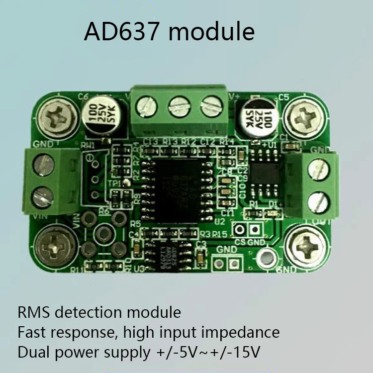
The AD637 rms measurement module converts the externally input AC signal rms value into a DC signal output, which can calculate the true rms value of various complex waveforms. The measurable input signal has an effective value of up to 7V, and for a 1VRMS signal, its -3dB bandwidth is up to 8MHz. In addition, the AD637 can reduce the quiescent current from 2.2mA to 350uA through the Chip Select (CS) pin. Therefore, it has a wide range of applications in data acquisition and instrumentation.
Features
(1) Measuring response speed is fast;
(2) The bandwidth within the measurement accuracy range is wider;
(3) high input impedance;
(4) A variety of filter circuits ensure measurement accuracy;
(5) By default, the potentiometer calibration is removed. This is a troublesome operation.
The main features:
(1) Wide power supply range: ±5V ~ ±15V; wide measuring range: 0 ~ 7Vrms.
When the ±5V power supply, the input RMS voltage range: 0 ~ 1.4Vrms;
When the power is supplied from ±12V to ±15V, the input rms voltage range is 0 ~ 7Vrms.
(2) It can measure DC signal (DC) and AC signal (AC).
(3) The highest measurement accuracy: <1%.
(4) The response speed is fast, and the slowest response speed is measured: <200ms.
(5) Maximum 3dB bandwidth: 8MHz.
(6) Output DC voltage ripple is small: less than 2mV.
(7) The module input has an op amp buffer, so the module input impedance is high: 10MΩ; the module is buffered by the op amp, so the module has a strong load capacity: 100Ω ~ +∞.
(8) The input and output interfaces are flexible and adopt two forms, one is the terminal interface (default), and the other is the SMA interface (the default is not soldered).
(9) With chip select function: can reduce power consumption by controlling chip select pin, the default chip select is valid, reserved (not soldered) pin interface for chip select control; reserved output voltage RMS calibration function : Manual adjustment of potentiometer calibration, since the on-board circuit design ensures measurement accuracy, the potentiometer is also not soldered by default.
(10) This module is designed with a jack GND for plugging the multimeter grounding pen to facilitate user testing.
(11) Module size: 5cm × 3cm.
(12) The appropriate module can be customized according to the actual needs of the user. Due to the cumbersome debugging process, a certain customization fee is required.
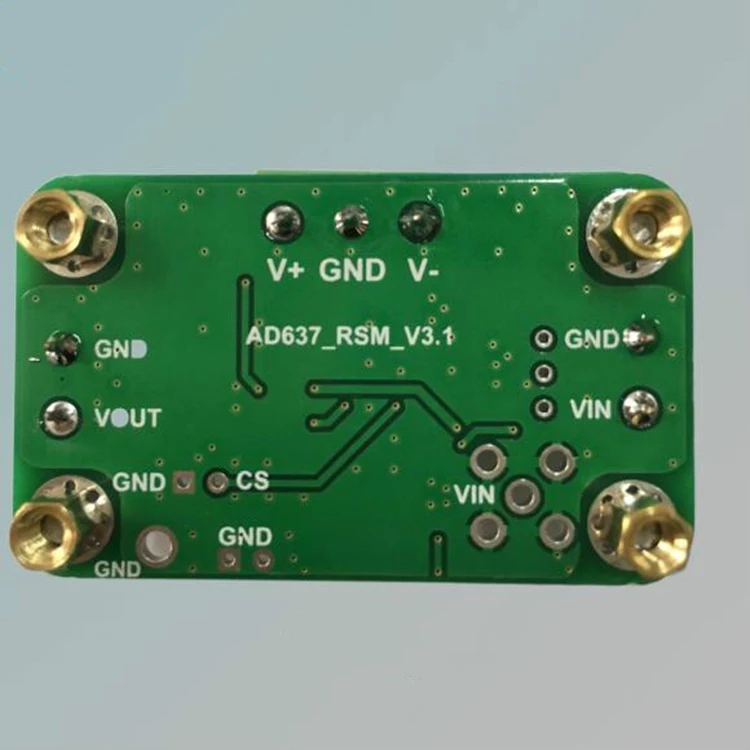
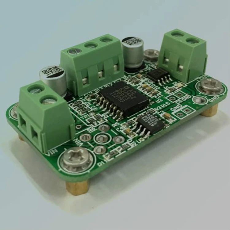
2 module interface
The modules are shown as shown in the figure.

Schematic diagram of module interface
3 Module Interface Connection Method

ModularTest connectionSketch Map
\4 Module debugging effect
\Module test input waveform is bipolar sine wave, frequency range0 ~ 8MHzAccording to the chip manuals, the input valid values are given respectively.10mV,100mV,1V,3Vand7VWhen the oscilloscope and digital multimeter test results.
Test conditions: sinusoidal input; DC voltage regulator ripple2.5mVWithin; using radio frequency wire connection.
The following test results will be slightly different due to device differences.
| \ Input valid value is 10 mV \ | \ Input valid value is 100 mV \ | ||
| \ frequency range \ | \ Error range \ | \ frequency range \ | \ Error range \ |
| \ 0—10kHz \ | \ 1% within \ | \ 0—80kHz \ | \ 1% within \ |
| \ 10kHz—20kHz \ | \ 2% within \ | \ 80kHz—200kHz \ | \ 2% within \ |
| \ 20kHz—60kHz \ | \ 10%within \ | \ 200kHz—500kHz \ | \ 10%within \ |
| \ 120kHzAbout \ | \ -3dB \ | \ 1MHzAbout \ | \ -3dB \ |
| \ Input valid value is 1V \ | \ Input valid value is 3V \ | ||
| \ frequency range \ | \ Error range \ | \ frequency range \ | \ Error range \ |
| \ 0—300kHz \ | \ 1% within \ | \ 0—350kHz \ | \ 1% within \ |
| \ 300kHz—2.5MHz \ | \ 2% within \ | \ 350kHz—1.6MHz \ | \ 2% within \ |
| \ 2.5MHz—4.3MHz \ | \ 10%within \ | \ 1.6MHz—2.2MHz \ | \ 10%within \ |
| \ 8MHz \ | \ -3dB \ | \ 3.2MHz \ | \ +3dB \ |
| \ Input valid value is 7V \ | \ \ | \ \ | |
| \ frequency range \ | \ Error range \ | \ \ | \ \ |
| \ 0—400kHz \ | \ 1% within \ | \ \ | \ \ |
| \ 400kHz—1MHz \ | \ 2% within \ | \ \ | \ \ |
| \ 1MHz—1.6MHz \ | \ 10%within \ | \ \ | \ \ |
| \ 2.2MHzAbout \ | \ +3dB \ | \ \ | \ \ |

Output waveform when input 100mVrms sine wave signal

Output when input 100mVrms sine wave signalEffective value

10mVrmsComparison of Input and Output with 7Vrms (51/2 Digital Multimeter)
\
Input 10mVrms→ Response time of 7Vrms handover

Смотрите так же другие товары: