
10 шт. релейный модуль 5 в 1 2 4 8 каналов с оптроном выход Новый для arduino |
506,11 - 2 919,64 руб. / набор

Новое поступление

Магазина Module Factory Store работает с 05.05.2014. его рейтинг составлет 95.22 баллов из 100. В избранное добавили 634 покупателя. Средний рейтинг торваров продавца 4.8 в продаже представленно 988 наименований товаров, успешно доставлено 8853 заказов. 251 покупателей оставили отзывы о продавце.
Характеристики
*Текущая стоимость 248,50 уже могла изменится. Что бы узнать актуальную цену и проверить наличие товара, нажмите "Добавить в корзину"
| Месяц | Минимальная цена | Макс. стоимость | Цена |
|---|---|---|---|
| Sep-17-2025 | 295.41 руб. | 310.21 руб. | 302.5 руб. |
| Aug-17-2025 | 293.49 руб. | 308.57 руб. | 300.5 руб. |
| Jul-17-2025 | 246.75 руб. | 258.27 руб. | 252 руб. |
| Jun-17-2025 | 288.84 руб. | 302.26 руб. | 295 руб. |
| May-17-2025 | 250.34 руб. | 263.43 руб. | 256.5 руб. |
| Apr-17-2025 | 283.47 руб. | 297.29 руб. | 290 руб. |
| Mar-17-2025 | 280.12 руб. | 294.64 руб. | 287 руб. |
| Feb-17-2025 | 278.68 руб. | 292.64 руб. | 285 руб. |
| Jan-17-2025 | 275.9 руб. | 289.96 руб. | 282 руб. |
Описание товара


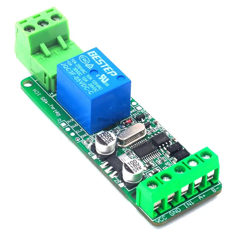
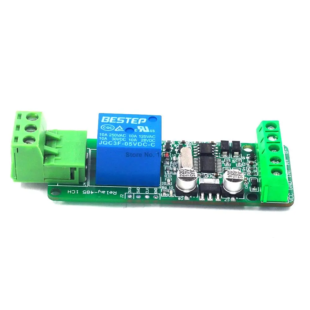
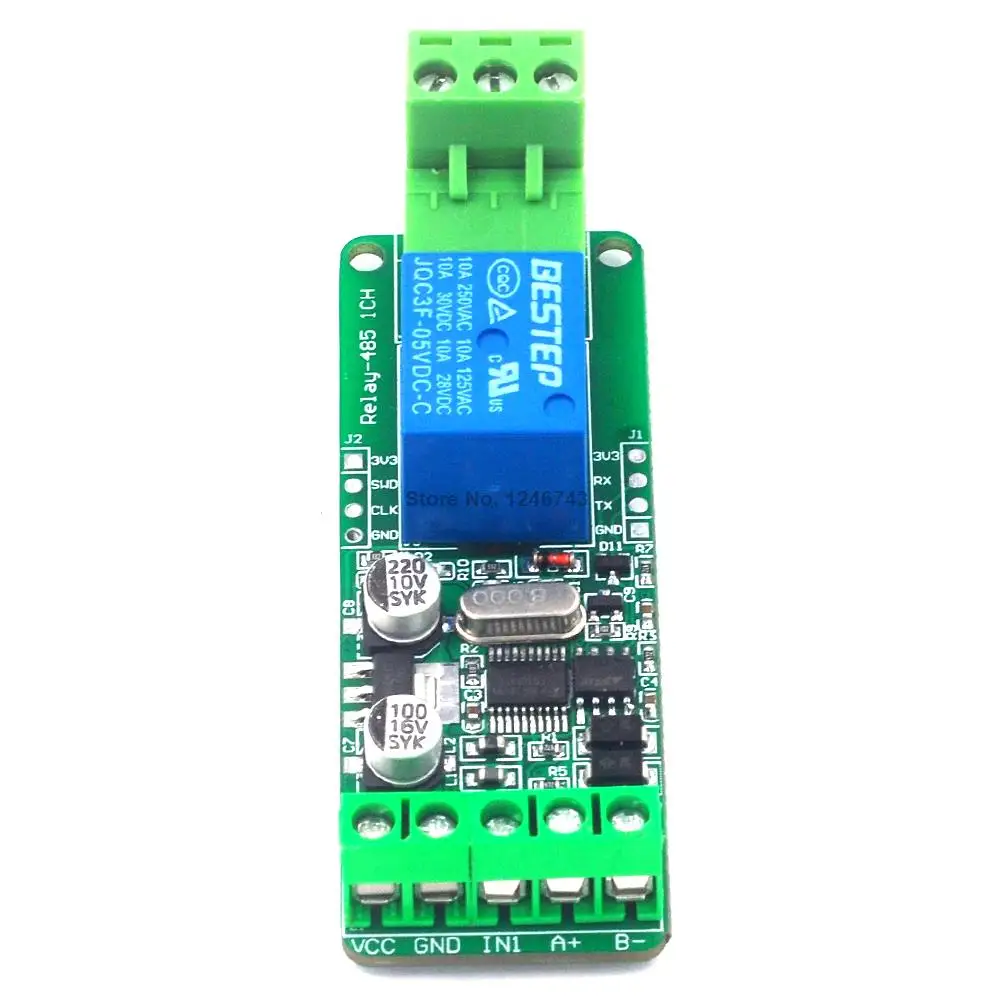
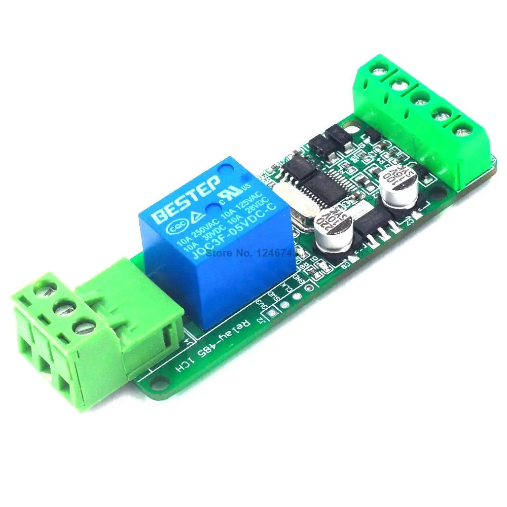
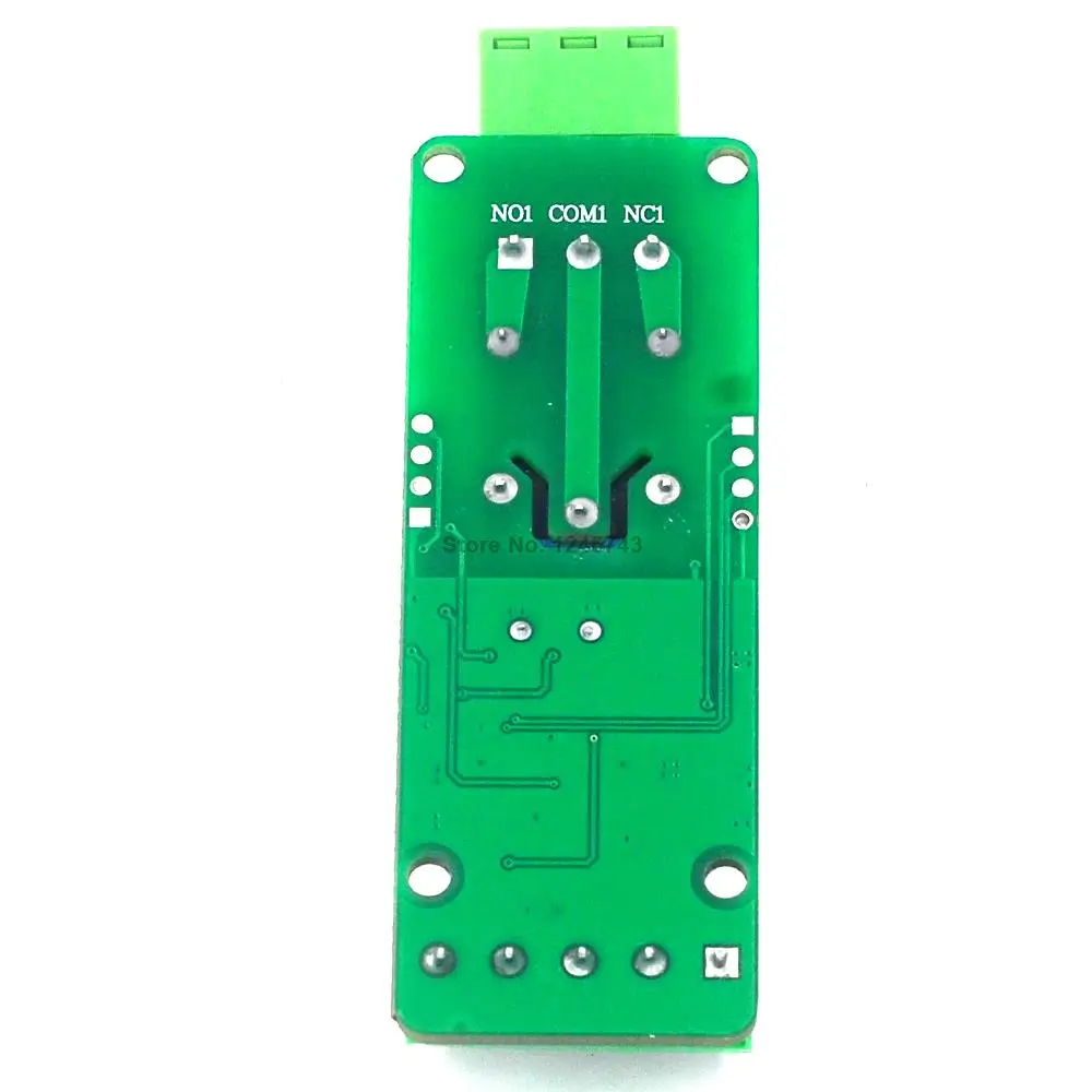
Input and output wiring and function description:
Output section: NC (normally closed) COM (common foot) N0 (normally open)
Load 220V 10A is recommended to be below 220V 6A
1. Just a switch is turned off and off without any voltage output.
2. The relay can only be controlled to open and close by 485 communication.
3. By default, NC COM is turned on. When 485 sends an open command, NC and COM are disconnected, and NO and COM are connected. on the contrary.
Input section: IN1 is connected to a switch or voltage signal (3V - 30V),
1. The status of the switch can only be read by the computer. The relay cannot be controlled. If necessary, the relay can be controlled to communicate with the store.
2. IN1 switch (no voltage signal): IN1 is connected to VCC computer to get 1 otherwise 0
Hardware resources:
1. RS485 communication interface
2. TTL communication interface
3. 1 input
4. 1 output
5. A user LED indicator
6. A STM32F030F4 microcontroller
7.1 relay status indicator LED lights
8. Power terminal interface (12V power supply)
Modbus RTU instruction
Baud rate: 9600 8 NONE 1
Hexadecimal transmission
Hexadecimal reception
Steps:
1. Software set communication baud rate
2. Set the address (device address used for communication, the default address is 01)
/************************************************* ******************/
Note: Only one device is connected, otherwise the address will be set.
Set the address to: 01
00 10 00 00 00 01 02 00 01 6A 00// Modified to 01
Set the address to: 02
00 10 00 00 00 01 02 00 02 2A 01// Modified to 02
Set the address to: 03
00 10 00 00 00 01 02 00 03 EB C1// Modified to 03
Read address
00 03 00 00 00 01 85 db
return:
00 03 02 00 01 44 44 //01 is the address
/************************************************* ******************/
/************************************************* ******************/
The meaning of each byte:
[Address 1]
//--------------------------------------------
Relay No. 1 is on: 01 05 00 01 01 00 9d 9a
Byte 1: Address
Byte 2: Function?
Byte 3 4: Register Address
Byte 5 6: Register Data
Byte 7 8: CRC check
//========================================================= ==============
[Address 1]
//--------------------------------------------
Relay No. 0 is on: 01 05 00 00 FF 00 8C 3A
Relay No. 0 is closed: 01 05 00 00 00 00 CD CA
//--------------------------------------------
Relay No. 1 is on: 01 05 00 01 FF 00 DD FA
Relay No. 1 is closed: 01 05 00 01 00 00 9C 0A
//-------------------------------------------
Relay No. 2 is on: 01 05 00 02 FF 00 2D FA
Relay No. 2 is closed: 01 05 00 02 00 00 6C 0A
//-------------------------------------------
Relay No. 3 is open: 01 05 00 03 FF 00 7C 3A
Relay No. 3 is closed: 01 05 00 03 00 00 3D CA
//-------------------------------------------
Relay No. 4 is on: 01 05 00 04 FF 00 CD FB
Relay No. 4 is closed: 01 05 00 04 00 00 8C 0B
//--------------------------------------------
Relay No. 5 is on: 01 05 00 05 FF 00 9C 3B
Relay No. 5 is closed: 01 05 00 05 00 00 DD CB
//-------------------------------------------
Relay No. 6 is on: 01 05 00 06 FF 00 6C 3B
Relay No. 6 is closed: 01 05 00 06 00 00 2D CB
//-------------------------------------------
Relay No. 7 is on: 01 05 00 07 FF 00 3D FB
Relay No. 7 is closed: 01 05 00 07 00 00 7C 0B
//-------------------------------------------
/************************************************* ***********************/
Read No. 0 relay status: 01 01 00 00 00 01 FD CA
Read relay status No. 1: 01 01 00 01 00 01 AC 0A
Read the status of relay No. 2: 01 01 00 02 00 01 5C 0A
Read relay status No. 3: 01 01 00 03 00 01 0D CA
Read relay status No. 4: 01 01 00 04 00 01 BC 0B
Read relay status No. 5: 01 01 00 05 00 01 ED CB
Read relay status No. 6: 01 01 00 06 00 01 1D CB
Read relay status No. 7: 01 01 00 07 00 01 4C 0B
Read all relay status: 01 01 00 00 00 08 3D CC
/************************************************* **********************/
Flash instruction:
Description: Close immediately after turning on, 100MS is one unit [1 represents 100MS]
Address 1:
Relay No. 0 is flashed off: 01 05 02 00 07 00 CE 42 //700MS = 7*100MS = 700MS
Relay No. 1 is flashed off: 01 05 02 01 08 00 9A 72 //800MS
Return: same as sending the command
Address 2:
Relay No. 0 is flashed off: 02 05 02 00 05 00 CF 11 //500MS
Relay No. 1 is flashed off: 02 05 02 01 06 00 9E 21 //600MS
//========================================================= =======================
Fully extinguished: 01 0F 00 00 00 08 01 00 FE 95
Full light: 01 0F 00 00 00 08 01 FF BE D5
/************************************************* *********************/
Single flip instruction:
Relay No. 0 flipped: 01 05 00 00 55 00 F2 9A
Relay No. 1 flipped: 01 05 00 01 55 00 A3 5A
Relay No. 2 flipped: 01 05 00 02 55 00 53 5A
Relay No. 3 flipped: 01 05 00 03 55 00 02 9A
Relay No. 4 flipped: 01 05 00 04 55 00 B3 5B
Relay No. 5 flipped: 01 05 00 05 55 00 E2 9B
Relay No. 6 flipped: 01 05 00 06 55 00 12 9B
Relay No. 7 flipped: 01 05 00 07 55 00 43 5B
All flip instructions:
01 05 00 00 5A 00 F7 6A
/************************************************* ********************/
Read all interfaces input status
Send: 01 02 00 00 00 08 79 CC //Read 8 input states
Back: 01 02 01 00 A1 88


Смотрите так же другие товары:


