AASD - 20A AC Servo Driver Motor driver for 130ST AC220V motor |
13560.75
Новое поступление

Магазина SuperMicro Store работает с 31.07.2019. его рейтинг составлет 96.29 баллов из 100. В избранное добавили 1515 покупателя. Средний рейтинг торваров продавца 4.8 в продаже представленно 877 наименований товаров, успешно доставлено 29185 заказов. 15448 покупателей оставили отзывы о продавце.
Характеристики
*Текущая стоимость 357.57 уже могла изменится. Что бы узнать актуальную цену и проверить наличие товара, нажмите "Добавить в корзину"
| Месяц | Минимальная цена | Макс. стоимость | Цена |
|---|---|---|---|
| Aug-17-2025 | 453.53 руб. | 462.1 руб. | 457.5 руб. |
| Jul-17-2025 | 368.54 руб. | 375.87 руб. | 371.5 руб. |
| Jun-17-2025 | 446.6 руб. | 455.48 руб. | 450.5 руб. |
| May-17-2025 | 443.62 руб. | 452.84 руб. | 447.5 руб. |
| Apr-17-2025 | 353.94 руб. | 360.36 руб. | 356.5 руб. |
| Mar-17-2025 | 436.11 руб. | 445.47 руб. | 440.5 руб. |
| Feb-17-2025 | 432.47 руб. | 441.62 руб. | 436.5 руб. |
| Jan-17-2025 | 428.38 руб. | 437.71 руб. | 432.5 руб. |
Описание товара


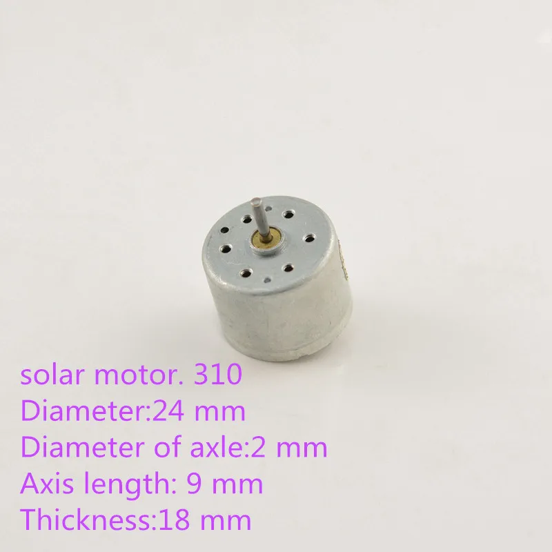
Brand NameNoneModel Number16 PWMMotor TypeAC MotorMeasurement unitpiece/piecesSold insell_by_pieceEach pack1Package weight0.018Package size - length (cm)12Package size - width (cm)10Package size - height (cm)5420,21 ₽-15% another 1 day420,21 ₽-15% another 1 day357,57 ₽357,57 ₽there are seller's coupons
Delivery to Moskva g
17 Jul - 314,94 ₽Delivery to a Post office
11 Jul - 314,94 ₽Self-pickup
90-Day Buyer Protection5,0
1 review10000All stars
In general, the goods are norms, but it has been very long or two months, so Evaluation 4
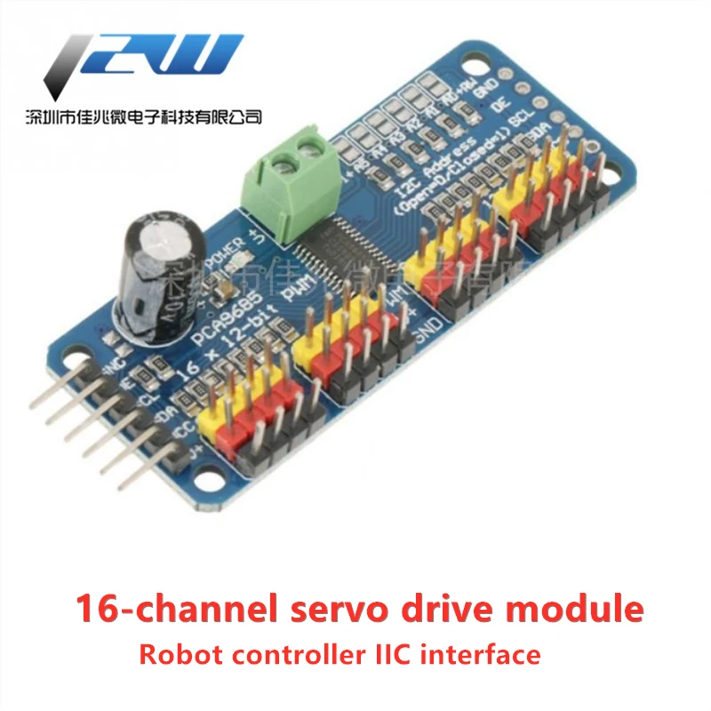
Show moreInstructions for 16-channel PWM servo driver board (PCA9685)
Overview
It is not difficult to drive the servo with the Arduino library. If you need to drive a lot of motors, you need to occupy more pins, which will also affect the Arduino's processing power. The special servo driver board solves this problem well.
This servo driver board uses the PCA9685 chip, which is a 16-channel 12-bit PWM servo driver, which can drive 16 servos through 2 pins through I2C. Not only that, you can also cascade up to 62 driver boards by cascading, which can drive a total of 992 servos!
Driver board connected with Arduino
This PWM driver board uses I2C mode, so only 4 wires are needed to connect to the Arduino device:
"Classic" Arduino pin method: + 5v-> VCC GND-> GND Analog 4-> SDA Analog 5-> SCL Old Mega pin method: + 5v-> VCC GND-> GND Digital 20-> SDA Digital 21-> SCL R3 and later Arduino pin method (Uno, Mega & Leonardo): (These boards have dedicated SDA and SCL pins) + 5v-> VCC GND-> GND SDA-> SDA SCL-> SCL
The VCC pin only supplies power to the chip. If you want to connect the servo or LED lights, use the V + pin to supply power. The V + pin supports a 3.3 ~ 6V power supply (5V when the chip is at a safe voltage). We recommend to supply power through an external power supply terminal.
Power supply part
The design voltage of most servos is 5 ~ 6V, especially when multiple servos are running at the same time, a high-power power supply is required. If you directly use the Arduino 5V pin to directly supply power to the servo, some unpredictable problems will occur, so we recommend that you can have a suitable external power supply for the driver board.
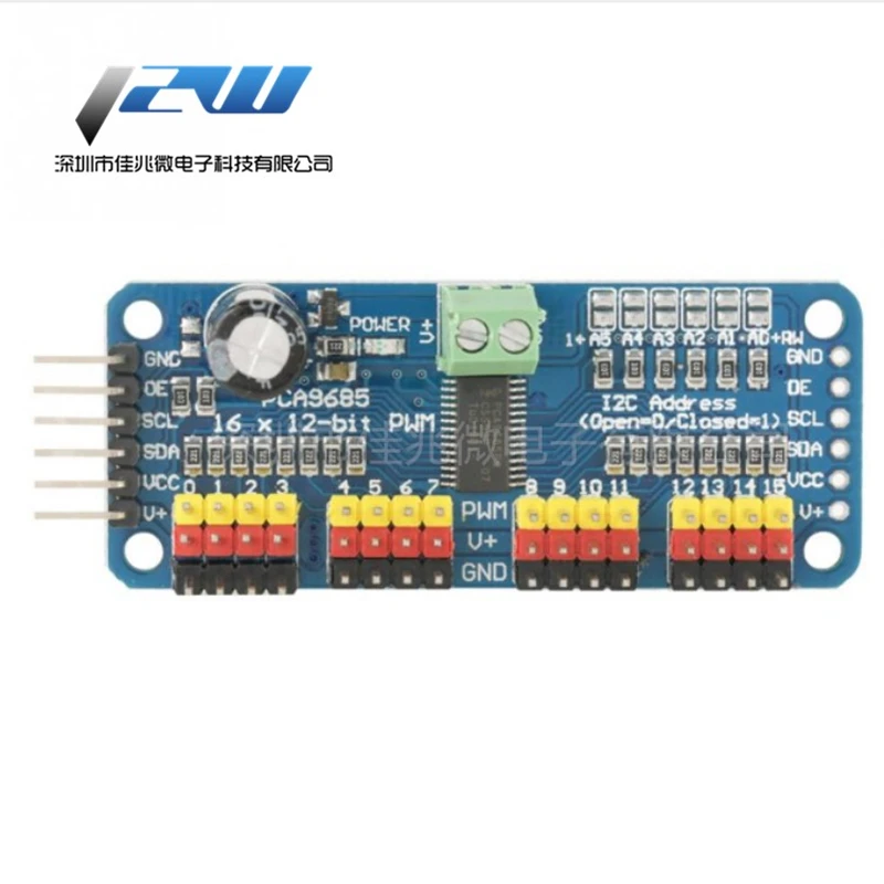
Connect the servo
Most servos are connected using standard 3-wire female plugs, as long as they are inserted into the driver board according to the corresponding pins. (The ground wire is generally black or brown, and the signal wire is generally yellow or white)
Up to 16 servos can be added on one driver board.
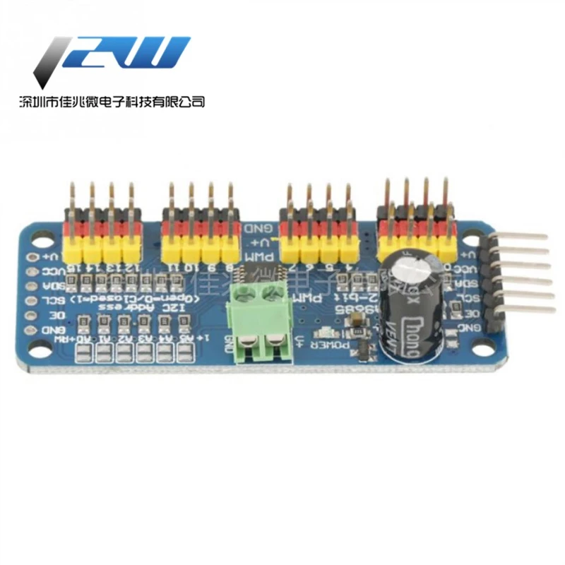
Drive board cascade
Multi-drive board cascade (up to 62 cascades) can provide you with greater scalability, the connection method is shown in the following figure.
Assign an address to the driver board
Each driver board in the cascade needs to have a unique access address. The initial I2C address of each driver board is 0 × 40, and the I2C address can be modified by the jumper in the upper right corner. Connect a jumper with solder to indicate a binary number "1".
Board 0: Address = 0 × 40
Offset = binary 00000 (default)
Board 1: Address = 0 × 41 Offset = binary 00001 (As shown above, connect A0)
Board 2: Address = 0 × 42 Offset = binary 00010 (connect A1)
Board 3: Address = 0 × 43 Offset = binary 00011 (connect A0 and A1)
Board 4: Address = 0 × 44 Offset = binary 00100 (connect A2)
And so on. . .
Code example:
#include
Смотрите так же другие товары: