
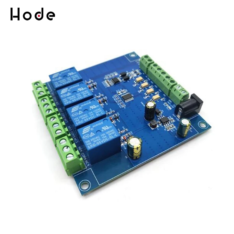
Single Turn Resistor 50W 10 Ohm Adjustable Taper Ceramic Disk Rheostat | Инструменты
1 366,71 руб.

Новое поступление

Магазина Hode Store работает с 18.08.2018. его рейтинг составлет 91.87 баллов из 100. В избранное добавили 751 покупателя. Средний рейтинг торваров продавца 4.7 в продаже представленно 3024 наименований товаров, успешно доставлено 15494 заказов. 1537 покупателей оставили отзывы о продавце.
Характеристики
*Текущая стоимость 585,53 уже могла изменится. Что бы узнать актуальную цену и проверить наличие товара, нажмите "Добавить в корзину"
| Месяц | Минимальная цена | Макс. стоимость | Цена |
|---|---|---|---|
| Aug-15-2025 | 743.32 руб. | 758.31 руб. | 750.5 руб. |
| Jul-15-2025 | 603.28 руб. | 615.52 руб. | 609 руб. |
| Jun-15-2025 | 731.33 руб. | 746.81 руб. | 738.5 руб. |
| May-15-2025 | 725.28 руб. | 740.48 руб. | 732.5 руб. |
| Apr-15-2025 | 579.57 руб. | 591.55 руб. | 585 руб. |
| Mar-15-2025 | 714.66 руб. | 728.31 руб. | 721 руб. |
| Feb-15-2025 | 708.34 руб. | 722.71 руб. | 715 руб. |
| Jan-15-2025 | 702.69 руб. | 716.19 руб. | 709 руб. |
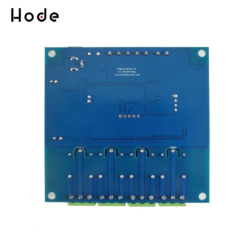
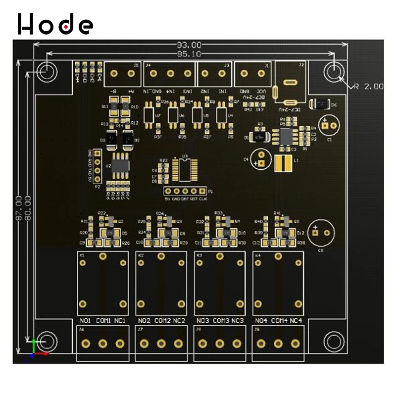
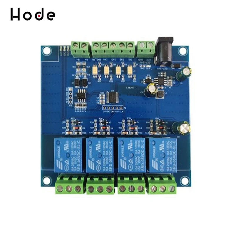
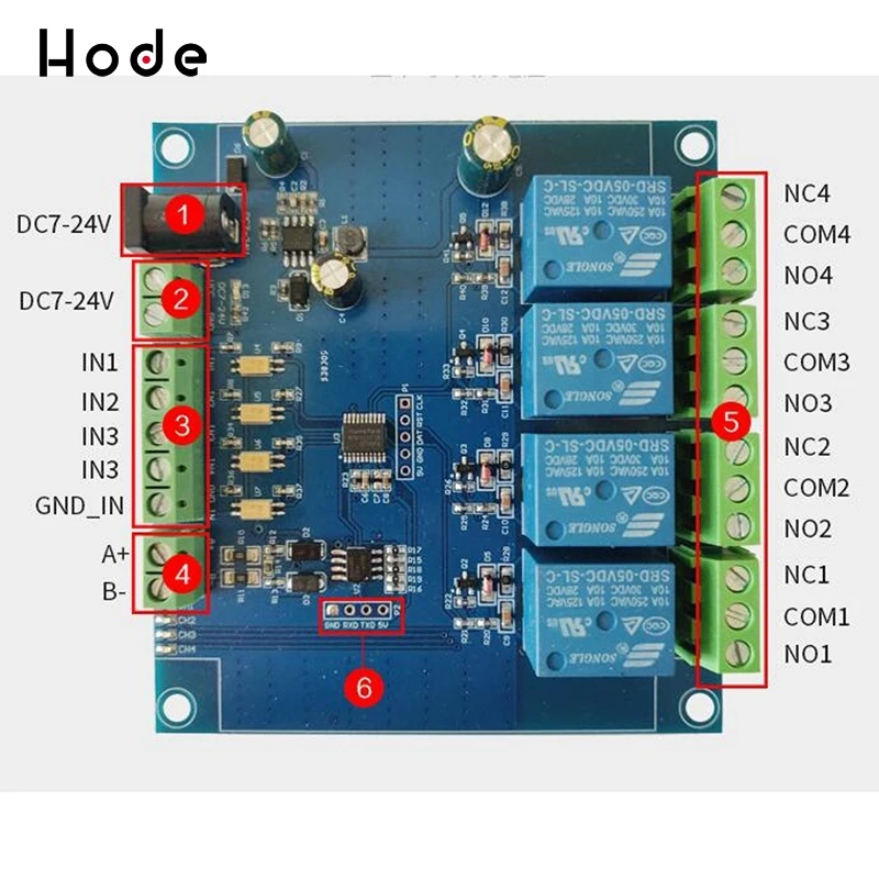
Описание товара


Description:


Смотрите так же другие товары:


