
200W/300W Вольтажный преобразователь трансформатор 220V в 110V снижения для путешествий с ЕС/США разъемом.
1366.35

Новое поступление

Магазина DIYHUB Store работает с 14.10.2020. его рейтинг составлет 91.75 баллов из 100. В избранное добавили 593 покупателя. Средний рейтинг торваров продавца 4.7 в продаже представленно 3467 наименований товаров, успешно доставлено 1572 заказов. 679 покупателей оставили отзывы о продавце.
Характеристики
*Текущая стоимость 3564.51 уже могла изменится. Что бы узнать актуальную цену и проверить наличие товара, нажмите "Добавить в корзину"
| Месяц | Минимальная цена | Макс. стоимость | Цена |
|---|---|---|---|
| Sep-18-2025 | 4241.22 руб. | 4453.55 руб. | 4347 руб. |
| Aug-18-2025 | 4206.87 руб. | 4416.79 руб. | 4311 руб. |
| Jul-18-2025 | 3528.70 руб. | 3704.90 руб. | 3616 руб. |
| Jun-18-2025 | 4134.88 руб. | 4341.9 руб. | 4237.5 руб. |
| May-18-2025 | 3600.0 руб. | 3780.93 руб. | 3690 руб. |
| Apr-18-2025 | 4063.27 руб. | 4266.75 руб. | 4164.5 руб. |
| Mar-18-2025 | 4027.63 руб. | 4228.89 руб. | 4127.5 руб. |
| Feb-18-2025 | 3992.84 руб. | 4192.93 руб. | 4092 руб. |
| Jan-18-2025 | 3956.60 руб. | 4154.79 руб. | 4055 руб. |
Описание товара


MODBUS Distributed module testing software

chart1 MB10DI4RO - Setting interface

chart2 MB10DI4RO - Acquisition and control interface
Chapter one Product introduction
One. summary
MB10DI14RO 10Circuit switch input acquisition and4Circuit relay output module,Collectable10Dry contact or wet node signal(Active or passive input);As dry contact input or sensor(NPNperhapsPNP)Input can be set with jumper common positive or negative input;As an active input, the polarity is automatically converted,Switching without jumper;4The relay can pass throughMODBUSThe bus can be controlled;Module usesModbus-RTUcommunication,It can be directly adaptedPLC、DCSAnd a variety of domestic configuration software。
Switch input and relay output、Power input、RS485Communication electrical signals are isolated from each other,Effectively suppress all kinds of series mode and common mode interference,It also ensures that the module works reliably。
Two. characteristic
1.useModbus-RTUagreement,It can be directly adaptedPLC、DCSAnd a variety of domestic configuration software。
2.signal acquisition 、Relay output、Power Supply、RS485Communication electrical signals are isolated from each other。
3.RS485The communication signal output interface adopts over-voltage and over-current protection。
4.Input signal type and communication format can be set by software。
5.Power polarity protection。
6.Flexible input signal setting
A.When set to active input,The input signal can be a common positive input or a common negative input at the same time。
B.When set to dry contact input,Just short-circuitDIInput toDIVCCJust fine。
Three. Technical index
| project |
parameter |
| Signal input |
1.Input channel:10Switch input of dry contact or wet node 2.Signal type:Automatic identification of common negative or common positive input polarity 3.signal level :High level(10V ~ 30V) Low level(0V ~ 3V) 4. Sampling rate:1000HZ 5. Isolated voltage protection:1000V |
| signal output |
1.Output channel:4Circuit normally open relay output 2.Load capacity:Resistive load250V/8A inductive load 250V/3A 3. Isolated voltage protection:1000V |
| Communication output |
1.Communication protocol:MODBUS-RTU 2.Interface type:quarantineRS485communication,The output interface adopts over-voltage and over-current double protection 3.Baud rate: 1200bps、2400bps、4800bps、9600bps、19200bps. 38400bps、57600bps、115200bps 4.Check bit: No check、Even check、Odd check 5.Setting method:Module address、Baud rate、The check bit is set by software 6.Communication distance:@9600bps 1200rice 7. Electrical isolation protection:1000V |
| Module size |
Individual module size:115mm*90mm*40mm |
| Installation mode |
1. DIN-Rail Mounting :standard35mm DINDIN-Rail Mounting 2. Screw fixation(Length and width):105mm*70mm |
| work environment |
temperature:-20 ~ +60℃ humidity:15~85%(No condensation) |
| Working power supply |
1.Supply voltage:10V~30VWide range power supply,With power polarity protection 2.Power consumption:less than3.5W |
| Module net weight |
220gram |
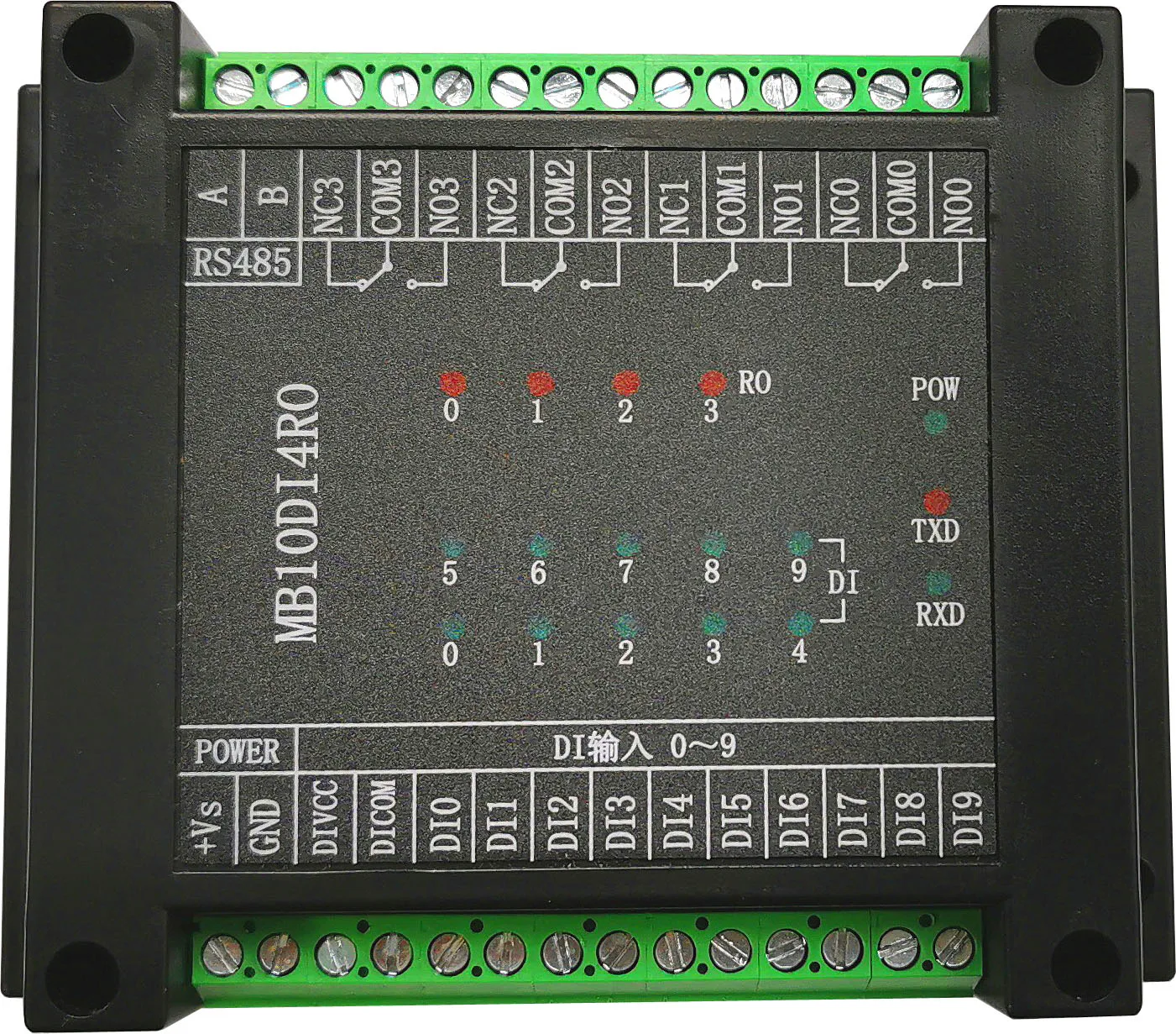
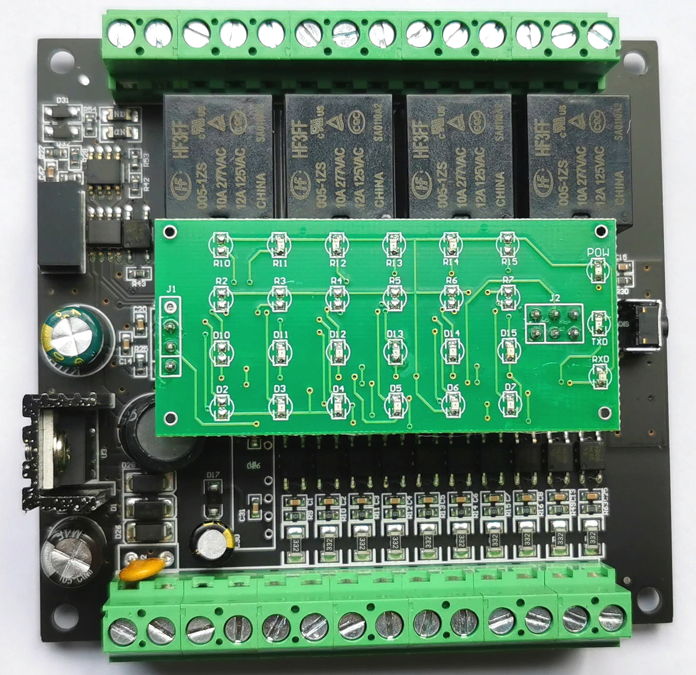
Four. Product appearance

Five. Module peripheral wiring diagram
1.Switch input wiring description

2.Relay output connection(Normally open)

3. Connection of communication and power supply

Six. Function description of module indicator and switch
1.POW/SET; Module working status indicator
A.The green light is on:The module is working in the running state。
2. TXD/RXD: Communication status indication
A. The green light is flashing:Communication received data
B. The red light is flashing:The module is sending data
C. The green light is always on:DATA+andDATA-Uplink communicationRS485The wires are connected reversely or the wiring is broken。
3.Purpose of module left reset switch
A.Communication parameters after reset:address:1、Baud rate:9600bps、Check bit:nothing。
B.When communication parameters(Module address、Baud rate、Check bit)Do not know or the communication parameters are set incorrectly,Unable to communicate with module,The solution is to reset the communication parameters;Locate the right reset module switch,Press and hold the module switch with a paper clip,5Second module[POW]The green light goes out and lights up again,Then release the reset switch,At this time, the communication parameters have been reset,At this time, the communication parameters of the module have been reset。
Seven. Schematic block diagram
Смотрите так же другие товары:


