

Новое поступление

Led Controller 44 Keys LED IR RGB Controler Lights Remote 44key Control Dimmer DC12V For 3528 5050 LEDStrip | Лампы и освещение
172,88 руб.

XH-A901 NE5532 Tone плата предусилителя Pre-amp с регулировкой громкости высоких басов
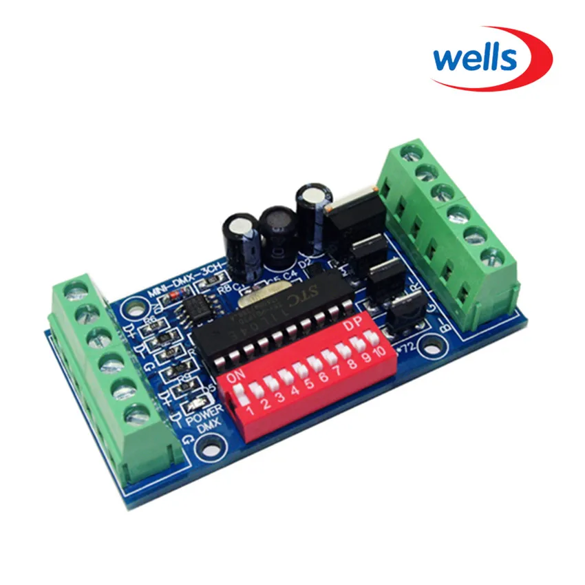
mini 3CH Easy dmx LED Controller subminiature RGB dmx512 decoder DC5V-24V for strip light | Лампы и освещение

Беспроводной светодиодный регулятор яркости V1 Mini DC5V/12V/24V 8A PWM + сенсорный
717,07 - 1 437,05 руб.

Светодиодный регулятор яркости Miboxer Mini FUT036 2 4 ГГц 12 В/24 В постоянного тока А ШИМ
569,71 - 1 493,95 руб.

DC12V 24V Waterproof IP68 RGB led amplifier for hard light strips flexible panel lights LED modules floodlights | Лампы и освещение
1 048,06 руб.

Smart WiFi Addressable RGB led контроллер полосы для WS2811 UCS1903 WS2812B SM16703 SK6812 Пульт дистанционного
Характеристики
DC 5V~24V Full color DMX 512 Decoder led strip dimmer to SPI module controller support WS2811 WS2812 WS2801 6803 IC | Лампы и
История изменения цены
*Текущая стоимость уже могла изменится. Что бы узнать актуальную цену и проверить наличие товара, нажмите "Добавить в корзину"
| Месяц | Минимальная цена | Макс. стоимость | Цена |
|---|---|---|---|
| Sep-18-2025 | 0.90 руб. | 0.64 руб. | 0 руб. |
| Aug-18-2025 | 0.72 руб. | 0.29 руб. | 0 руб. |
| Jul-18-2025 | 0.91 руб. | 0.37 руб. | 0 руб. |
| Jun-18-2025 | 0.89 руб. | 0.78 руб. | 0 руб. |
| May-18-2025 | 0.44 руб. | 0.85 руб. | 0 руб. |
| Apr-18-2025 | 0.22 руб. | 0.30 руб. | 0 руб. |
| Mar-18-2025 | 0.60 руб. | 0.4 руб. | 0 руб. |
| Feb-18-2025 | 0.21 руб. | 0.65 руб. | 0 руб. |
| Jan-18-2025 | 0.83 руб. | 0.43 руб. | 0 руб. |
Описание товара


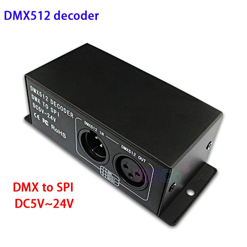
 Description:
DMX512 signal decoder using advanced microcomputer control technology, the widely used DMX512/1990 standard digital control signal into a variety of LED control chip control signal. Can be connected with the DMX digital console, and can increase the decoder constantly expanding the output channel, in order to achieve more dimming or a variety of program changes. When the decoder is not connected with the DMX console, the machine can be used as a synchronization controller, and can be used for the synchronization control of a plurality of decoders and LED lamps..
Technical Parameters
Description:
DMX512 signal decoder using advanced microcomputer control technology, the widely used DMX512/1990 standard digital control signal into a variety of LED control chip control signal. Can be connected with the DMX digital console, and can increase the decoder constantly expanding the output channel, in order to achieve more dimming or a variety of program changes. When the decoder is not connected with the DMX console, the machine can be used as a synchronization controller, and can be used for the synchronization control of a plurality of decoders and LED lamps..
Technical Parameters
|
Model |
6803 |
2811,2812,1903,1809 |
2801 |
|
Input Voltage |
DC5-24V |
||
|
Input Signal |
DMX512/1990 |
||
|
Output Signal |
6803 |
2811/2812/1903/1809 |
2801 |
|
Decode Channel |
510 |
510 |
510 |
|
Control LED QTY |
170 |
170 |
170 |
|
Control LED QTY |
Standard XLR-3 |
||
|
Size (mm) |
125*54*43(mm) |
||
|
Weight |
275g |
||
|
fittings |
A pair of XLR plugs |
||
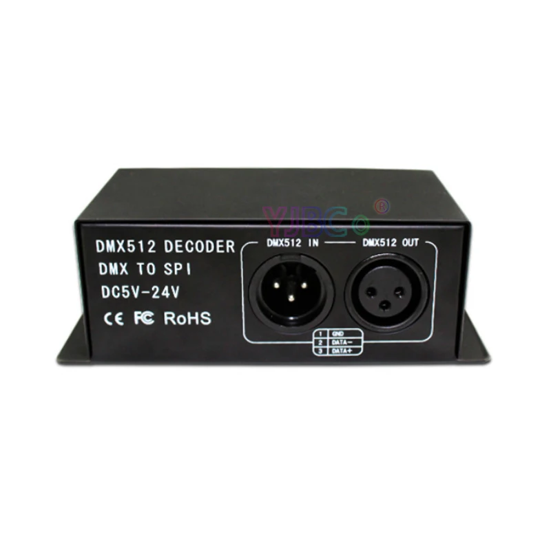
Connection description:
DMX Input/output interface:
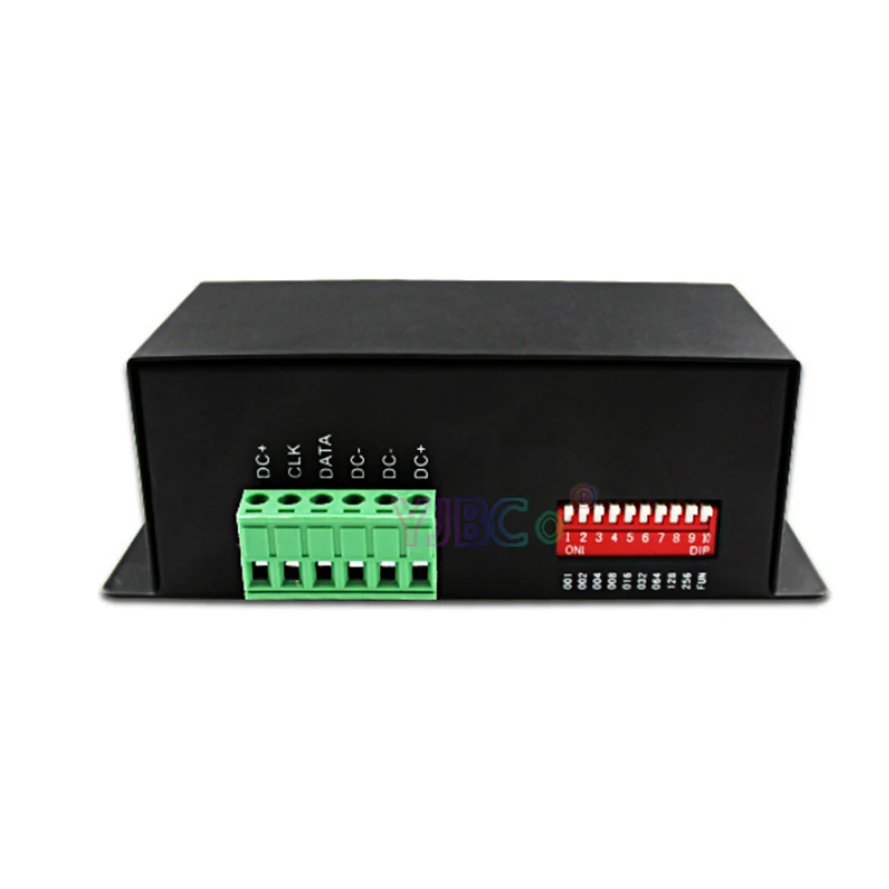
Address code and set feature service interface:

Power and Load interface:
Adopt male and female connector with screw.
Direction for use
This product is in compliance with DMX512 protocol, and compatible autoindex addressing and manual establishment address. Each universal DMX controller takes up 3 DMX addresses. It adopts 2 ways (auto-index addressing and code switch) to set up the address. When adopting the auto-index addressing, all switches are "off" status. When adopting the code switch to set up address, the 10th bit(FUN) is "off" status, and other 9 bits are binary value code switch which are used to set up the DMX starting address code. The first bit is the lowest order bit, and the ninth is the highest order bit. That can set up 511 address codes. The DMX starting address code is equal to the sum of 1st to 9th bit. If move down one bit of code switch ("ON" set "1"), you can get the place-value of this bit. If move up (set "0"), the place-value is 0. For example: if you want to set up DMX starting address code for 73, you should move down the 7th, 4th, and 1st bit of code switch for "1", and others for "0", Then the place-value's sum of 1st to 9th bit is 64+8+1. That is to say, the DMX512 starting address code is 73. (The correspondence dials code position is as follows) To choose the channel from the Dial in-line Package(DIP) Switch:|
Decimals |
1 |
2 |
3 |
4 |
5 |
6 |
7 |
8 |
9 |
10 |
|
Weight-number |
1 |
2 |
4 |
8 |
16 |
32 |
64 |
128 |
256 |
FUN |
1. Example 1:
Like figure 1, to set up the DMX starting address code for 37, should move down the 6th, 3th, 1st bit for "1", others for "0". Then the place-value's sum of 1st to 9th bit is 32+4+1, as is for 37.

2. Example 2:
Like figure 2, to set up the DMX starting address code for 328, should move down the 9th, 7th, 4th bit for "1", others for "0". Then the place-value's sum of 1st to 9th bit is 256+64+8, as is for 328.

 Three. Conjunction Instruction:
Model 6803/2801 foreign output LPD6803 / WS2801 control signal, need four wires, the four lines, respectively:
|
DATA |
6803/2801 signal line |
|
CLK |
6803/2801 clock line |
|
GND |
With the positive pole is connected |
|
DC+ |
With the negative pole is connected |
Model 2811, 2812, 1903, 1809, foreign output 2811/2812/1903/1809 of the control signal, need three lines, the three lines, respectively:
|
DATA |
2811/2812/1903/1809 signal clock |
|
GND |
With the positive pole is connected |
|
DC+ |
With the negative pole is connected |


Package included:
1 * DMX512 decoder


Смотрите так же другие товары: